Controlling a pellet boiler system

Figure 1: The control logic for this system was based on a pellet boiler that operated under its own internal controller. That controller monitors two temperature sensors within the thermal storage tank. Graphics credit: John Siegenthaler, P.E.

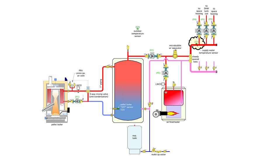
Figure 2: The control scheme in Figure 1 works, but it lacks the ability to draw the thermal storage tank down to significantly lower temperature under partial load conditions. The control method to remedy this limitation is outdoor reset. It can be deployed through sensor (S1), which measures supply water temperature to the distribution system. Graphics credit: John Siegenthaler, P.E.

Figure 3: This is one way in which a two-stage controller, operating on either outdoor reset control logic or setpoint logic, can be combined with a single-stage setpoint controller and some relays to: operate the pellet-fired boiler for relatively long cycles; automatically start the oil-fired boiler when necessary; and prevent heat produced by the oil boiler from moving into thermal storage. Graphics credit: John Siegenthaler, P.E.


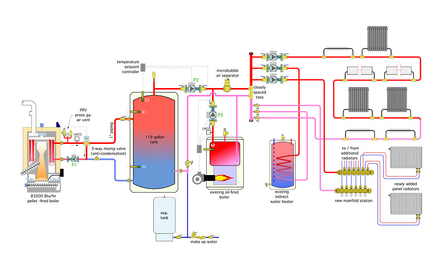
Last month we discussed a scenario in which a new pellet boiler would be added to an existing hydronic system with an oil-fired boiler. The piping for this system is shown in Figure 1.
The control logic for this system was based on a pellet boiler that operated under its own internal controller. That controller monitors two temperature sensors within the thermal storage tank. When the temperature at the upper sensor (S1) drops to some lower setpoint (such as 150° F), the pellet boiler fires. It remains in operation until the temperature at the lower sensor (S2) has climbed to some high temperature limit (such as 180°). This stacks the tank full of hot water before the boiler is turned off.
The objective is to create long on-cycles followed by long off-cycles, which increase the overall burn cycle efficiency of the boiler and reduces its emissions. There is no interconnection between the pellet boiler controls and the distribution system controls. Not all pellet-fired boilers have this control capability. However, external controls can create similar and arguably better control logic for the boiler.
The control logic for determining which heat source supplies the load(s), as described in the January column (“A simple boiler retrofit”), was very basic: Whenever there is a demand for space heating or domestic water heating, the appropriate zone circulator is turned on and power is applied to a temperature setpoint controller. The latter measures the water temperature in the upper portion of the thermal storage tank at sensor (S3). If that temperature is at or above some minimum value (such as 170°), circulator (P2) is turned on and heat is supplied from the tank to the load.
If the water temperature in the upper portion of the tank is below this setpoint by some differential (say 5°), circulator (P2) is off and the oil-fired boiler is turned on, along with circulator (P3). If the temperature at the top of the thermal storage tank later rises to the minimum setpoint plus a differential (in this case 170 + 5 = 175°), the setpoint controller brings the tank back online as the heat source and turns off the oil-fired boiler and its circulator.
Although this control scheme works, it lacks the ability to draw the thermal storage tank down to significantly lower temperature under partial load conditions. Doing so would improve the performance of the pellet boiler by reducing the number of start/stop cycles over the heating season.
Reset to the rescue
The control method to remedy this limitation is outdoor reset. It can be deployed through the sensor that measures supply water temperature to the distribution system. Figure 2 shows a portion of the same system with sensor (S1) in place.
The pellet boiler is turned on only when the thermal storage tank (which is heated by the pellet boiler) cannot maintain the required supply water temperature at sensor (S1). For space heating, this temperature can be reduced under partial load conditions, even for a system with fin-tube baseboard sized around a design load supply water temperature of 170° to 180°. For example, assuming an outdoor design condition of 0°, the required supply water temperature only has to be 125° when the outdoor temperature is 35°, and only about 98° when the outdoor temperature is 53°.
The heat-source control system also needs to turn on the oil-fired boiler if the thermal storage tank cannot maintain the target supply water temperature at sensor (S1). This is done using a two-stage outdoor reset controller. This controller will attempt to create the target supply water temperature at sensor (S1) using the heat source wired to its first-stage contacts (in this case, the thermal storage tank). If it can’t do this within a relatively short time, the second-stage contacts in the controller close to turn on the oil-fired boiler.
The decision to close the second-stage contacts is based on PID logic, which determines the difference between the target temperature and the measured temperature at sensor (S1), how long that difference persists, and how fast it is changing. Small temperature differences that change quickly will delay or preclude use of second-stage heat input. Larger temperature differences that change slowly will hasten use of second-stage heat.
The control system must not permit heat produced by the oil boiler from being inadvertently transferred to the thermal storage tank. This is bad practice from the standpoint of thermodynamics. It converts a high-grade energy source (oil) into a low-grade form (heat) before such a conversion is necessary from the standpoint of meeting the load. Once this conversion takes place, it’s just a matter of time until the heat dissipates through the tank’s jacket, and thus is no longer available for controlled release into the building when and where it’s needed.
One way to prevent this is to turn off the circulator that brings heat from thermal storage to the distribution system whenever the oil-fired boiler is on. The distribution system can be supplied by the thermal storage tank orthe oil-fired boiler, but never both at the same time. This is simple to accomplish: Use a normally closed relay contact to interrupt power to circulator (P2) whenever the oil-fired boiler is active.
Figure 3 shows one way in which a two-stage controller, operating on either outdoor reset control logic or setpoint logic, can be combined with a single-stage setpoint controller and some relays to:
- Operate the pellet-fired boiler for relatively long cycles;
- Automatically start the oil-fired boiler when necessary; and
- Prevent heat produced by the oil boiler from moving into thermal storage.
Description of operation
Upon a call from any space-heating zone or the indirect water heater, the associated load circulator is turned on. An unpowered contact closes between the (XX) terminal in the multizone relay center. A 24 VAC signal passes through this contact to power up the two-stage reset controller. Circulator (P2) turns on to provide flow between the thermal storage tank and the distribution system. The supply water temperature at sensor (S1) is measured and compared to the target temperature calculated by the boiler reset controller. If the measured temperature is a few degrees below the target temperature, the first-stage contacts in the reset controller close. This enables the pellet boiler to fire and turns on circulator (P1).
A motorized three-way valve controlled by the pellet boiler operates to keep the inlet water temperature to the boiler above 130° whenever possible to minimize flue gas condensation.
A call for pellet boiler operation also turns on a temperature setpoint controller that measures the water temperature in the lower portion of the thermal storage tank at sensor (S3) as seen in Figure 2. The purpose of this controller is to keep the pellet-fired boiler operating until the water temperature in the lower portion of the tank reaches a relatively high value (such as 175°), at which point the pellet boiler is turned off. This stacks the thermal storage tank full of relatively hot water. The objective is to lengthen the on-cycle and off-cycle of the pellet boiler. This improves its seasonal efficiency and reduces its emissions.
If the target temperature at the supply sensor (S1) is not being met by heat from the thermal storage tank, the second-stage contact of the reset controller closes. This powers up an external relay that, in turn, fires the oil boiler. Circulator (P3) is turned on by the limit controller on the oil boiler. This external relay also turns off circulator (P2), stopping flow between the thermal storage tank and distribution system. The load is now being fully assumed by the oil boiler. The first-stage contacts in the reset controller are still closed, so the pellet boiler also is firing to increase the water temperature in the thermal storage tank.
If the temperature at sensor (S1) rises quickly, the second-stage contacts in the reset controller will open in an attempt to shift the load back to the storage tank. Circulator (P2) will turn on. If the water temperature now supplied from the tank can sustain the water temperature at sensor (S1) close to the target value, the oil boiler will remain off. If not, the cycle described above repeats itself.
Whenever there is a call for domestic water heating from the aquastat on the indirect water heater, the target temperature at sensor (S1) shifts from a value based on outdoor temperature (e.g., outdoor reset control) to a fixed setpoint of 160°. This higher supply water temperature ensures adequate heat transfer through the coil of the indirect water heater. The reset controller (now operating in “setpoint” mode) will again attempt to meet this 160° temperature requirement at sensor (S1) using pellet-derived heat from thermal storage.
If it can’t, the DHW load is handed to the oil boiler by closure of the second-stage contacts. If the DHW load persists and the thermal storage tank warms up sufficiently, the second-stage contacts will open, handing the load back to the thermal storage tank. The assumption is it’s not wise to compromise DHW supply.
This system is, to some degree, constrained by existing hardware and piping. The control system was tailored to these constraints in a way that encourages long operating cycles for the pellet boiler, but quickly intercedes with heat input from the oil boiler when necessary to maintain comfort or adequate DHW delivery.
If given an opportunity to design an alternative system from scratch, there are definitely ways to improve performance and consolidate hardware. We’ll consider that in a future column.
Looking for a reprint of this article?
From high-res PDFs to custom plaques, order your copy today!


