The Glitch and Fix: Overly complex

The Glitch:
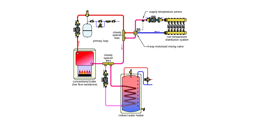
An installer uses a 4-way motorized mixing valve to interface between a conventional cast-iron boiler and a low temperature radiant panel system. That system also includes an indirect water heater. The system is installed with primary/secondary piping as shown. The mixing valve is located close to the boiler. Can you spot at least four details that are either incorrect, missing, inefficient or unnecessary?
> Figure 1
The Fix:
4-way motorized mixing valves are designed to create two mixing points within the valve body: One to regulate system supply temperature and the other to boost boiler inlet temperature high enough to prevent sustained flue gas condensation. To accomplish the latter, the controller operating the valve's motor must sense and react to boiler inlet temperature. Thus a boiler inlet temperature sensor is required, and is shown in the fix drawing.
> Figure 2

Although a primary/secondary system would work, there are simpler and less costly methods to achieve hydraulic separation between the circulators when the boiler and header piping have low flow resistance.
Use a short and generously sized header between the boiler and 4-way valve. The combined effects of buoyancy and momentum exchange within the valve will generate sufficient flow through the cast iron boiler.
This eliminates the need for a primary loop and associated primary circulator. It also eliminates what would be reduced water temperature to the indirect water heater coil if the space heating subsystem is active, and the indirect water heater was not operated as a priority load.
In the glitch drawing, the primary loop circulator is pumping toward rather than away from the location where the expansion tank connects to the system. That’s definitely wrong. So is the placement of the secondary circulator serving the indirect water heater. Secondary circulators should always direct water into the secondary circuit. This treats the upstream tee of the closely spaced pair as the point of no pressure change for the secondary circuit, allowing pressure within the secondary circuit to increase when its circulator is operating.
The supply temperature sensor is located immediately downstream of the 4-way mixing valve in the glitch drawing. Although mixing has begun by the time flow passes this sensor location, it may not be complete, and thus the sensor may not be sensing the final blended temperature supplied to the manifold station. It’s always good practice to install the supply temperature sensor downstream of the distribution circulator to ensure complete mixing has occurred before flow passes the sensor.
Finally, purging valves have been added to the return ends of both load circuits in the fix drawing.
Please read here to view The Glitch and Fix: September 2019 in pdf form.
Looking for a reprint of this article?
From high-res PDFs to custom plaques, order your copy today!


