The Glitch and Fix: Hardware heavy


The Glitch:
A client asks a heating contractor to set up a floor heating system for a new 7,500 square foot machine shop. The slab is 6-inches thick, and the entire shop will be controlled as a single zone with no temperature setbacks. The supply water temperature to the slab at design load is 105° F.
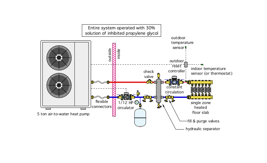
The client does not want any on-site fuel storage and asks the contractor to use an air-source heat pump as the system’s heat source. The contractor assembles the system shown in Figure 1.
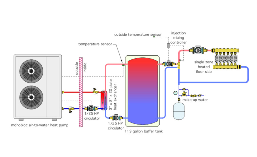
The air to water heat pump supplies a small brazed plate heat exchanger, which, in turn, delivers heat to a buffer tank. Two 1/25 horsepower zone circulators are used to create flow in these two circuits. The heat pump loop is protected from freezing by a 30% solution of propylene glycol antifreeze. The remainder of the system operates on water. The heat pump is turned on when the temperature sensor strapped to the upper tank header drops to 120º. It turns of when that sensor reaches 130º. The temperature supplied to the floor slab is regulated by a variable speed injection circulator, and is based on outdoor reset control.
Can you identify several missing or incorrect details? Can you spot any hardware that may not be necessary? How would you propose changing this design?
The Fix:
There’s a lot of unnecessary hardware in the original design.
First, consider the thermal mass of the slab versus that of a 119 gallon buffer tank. With a few simple calculations, it can be shown that the thermal mass of the floor slab is about 110 times greater than the thermal mass of a 119 gallon buffer tank. That slab can provide a huge stabilizing effect for the system while undergoing very minor temperature changes (perhaps only 2 to 4º F swings in average slab temperature). With this much mass in the system, there’s no need for a buffer tank.
Another poor decision was to operate the heat pump across a relatively high temperature range of 120-130º F, when the floor only needs 105º water at design load. The higher the fluid temperature required of the heat pump, the lower its coefficient of performance (COP).
There’s also going to be a significant “bottleneck” at the small (3-inch x 8-inch x 20 plate) heat exchanger shown between the heat pump and the buffer tank. A much larger and more expensive heat exchanger would be required to minimum the approach temperature difference between the heat pump loop and the secondary side of the heat exchanger. A better approach is to simply use an antifreeze solution in the entire system.
Other problematic details include:
- No expansion tank is the heat pump to heat exchanger loop;
- No pressure relief valve in the heat pump to heat exchanger loop;
- Inadequate circulator sizing (a 5 ton heat pump should operate at a flow rate in the range of 15 gpm). That’s not going to happen when a relatively small zone circulator is used). Same story on the secondary side of the heat exchanger;
- There’s no air vent at the top of the buffer tank;
- The supply temperature sensor for the injection controller should be downstream of the distribution circulator to ensure that complete mixing occurs before the temperature is measured;
- There are no air separators in the heat pump circuit or in the distribution system; and
- There is no purging valve in the distribution system.
One alternate design that greatly simplified the system relative to the original design is shown in Figure 2.

This system relies on the very high thermal mass of the distribution system to prevent short cycling of the heat pump. The distribution system uses constant circulation provided by an ECM type circulator. The ECM circulator with cut the electrical power required for circulation by about 50% relative to a standard circulator with a PSC motor. A larger circulator that provides 12 to 15 gpm through the heat pump is shown. This circulator could also be an ECM-type to further reduce pumping energy.
The water temperature supplied to the floor circuits is monitored by an outdoor reset controller equipped with indoor temperature sensing, or connected to a thermostat. This controller turns the heat pump on and off as required to ensure that the water temperature supplied to the slab is just warm enough for the current heating load. This keeps the heat pump operating at lower condenser temperatures, resulting in higher COPs. A reasonable differential of 5º between heat pump on and off allows the thermal mass of the slab to be “exercised” without causing wide swings in indoor comfort.
The entire system operates on antifreeze, which eliminates the complication, expense and thermal penalty of a heat exchanger between the heat pump and balance of system.
A hydraulic separator intercedes between the heat pump circulator (which has been increased in size to provide 12 to 15 gpm of flow through the 5-ton heat pump). This separator allows provides air separation and dirt separation for the system.
A check valve is installed to prevent reverse thermosiphoning of heat from the system back outside.
Flexible connectors have been installed to reduce vibration from the heat pump into the building.
Fill and purging valves on each side of the hydraulic separator allow both circuits to be quickly filled and purged.
And a pressure relief valve has been added to the system.
Download The Glitch and Fix: May 2020 in pdf form.
Looking for a reprint of this article?
From high-res PDFs to custom plaques, order your copy today!


-glitch.jpg?height=200&t=1644851746&width=200 "G&F February 2022 - Glitch")