The Glitch + The Fix: One shot after another

The Glitch:
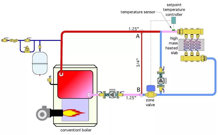
A technician encounters a system installed in the 1980s when radiant floor heating was relatively new in North America. The layout of that system is shown in Figure 1.
The temperature of water supplied to a radiant floor slab is controlled by sending repeated “pulses” of hot water into a circulating loop that supplies three embedded circuits. When the temperature at a sensor on the supply manifold reaches a setpoint, the zone valve closes. The radiant loop circulator continues to operate, allowing the temperature in the floor circuits to “coast” downward. When the temperature controller senses a drop of 10° F at the supply manifold, the zone valve reopens. The original installer purposely reduced the size of the piping between points A and B from 1 1/4 inch to 3/4 inch piping to induce a pressure differential that drives hot water from the boiler into the lower temperature portion of the system when the zone valve is open.
Can you identify some shortcomings of this system and suggest some improvements?

The Fix:
This system is an early form of what I call “on/off injection mixing.” Although a bit crude by modern standards, it was probably seen as state-of-the-art more than 40 years ago.
The pulses of hot water sent into the lower temperature portion of the system is akin to driving a car with only two possible power inputs: Idling or full power. That obviously doesn't make for a smooth ride. Fortunately — in this case — the high thermal mass of the concrete slab will partially dampen out these “pulses” of heat input. However, if applied to a low thermal mass distribution system, this approach would create wide and very noticeable variations in heat output.
For “smoother” heat input, the system should use a modulating device to control injection flow into the lower temperature portion of the system. A motorized valve with a modulating actuator is one possibility, a variable speed injection pump is another possibility. Both approaches have been used in many systems over many years.
Given that most injection controllers currently on the market are designed to work with standard circulators using PSC motors, and that those types of circulators are headed for extinction as more and more high efficiency ECM-based circulators enter the market, I’ll show the motorized modulating valve as the injection device in Figure 2.

The makeover uses a controller that measures supply water temperature as well as outdoor temperature and the temperature of water entering the boiler. This allows for either outdoor reset or setpoint control of the supply water temperature. It also allows the controller to prevent sustained flue gas condensation in the boiler by limiting the rate of heat injection as the slab is warming up. The original approach using “on/off” injection mixing cannot provide boiler protection because it has no way to accurately vary how much hot water is leaving the boiler loop and flowing into the lower temperature portion of the system.
The on/off zone valve in the original system is also likely to be cycled several thousand times each heating season. It’s just a matter of time until it fails. It could be replaced, but the same high cycling frequency awaits the replacement.
Another somewhat “crude” aspect of the original system is the pressure drop imposed by the reduced piping size between points A and B is somewhat arbitrary. A globe valve is a much more precise way to induce the pressure differential needed to push flow through the motorized valve as it opens.
Notice that the boiler circulator in the original installation is pumping into the boiler and toward the expansion tank. This will cause a drop in system pressure around the boiler loop when the boiler circulator is on. The proper relationship between the boiler circulator and tee where the expansion tank connects is shown in Figure 2.
Figure 2 also adds a purging valve in the lower temperature loop, and an air separator.
Looking for a reprint of this article?
From high-res PDFs to custom plaques, order your copy today!


