The gold standard: Protection from dissolved oxygen and debris in hydronic systems
Keeping hydronic systems healthy.

The DIRTMAG PRO separates both ferrous and non-ferrous debris and has 40% more magnetic power than earlier models, Caleffi notes. Purging the debris is easy and quick — simply remove the top insertion magnet and the magnetic band then open the drain valve to purge the captured impurities.
Water is the life-blood of hydronic systems. Just as we strive to maintain the health of our own circulatory systems, it’s important to maintain the health of the water-based solutions that circulate through the hydronic systems we construct and maintain.
Air separators and dirt separators — a fluid cleaning duo — help ensure maximum protection and efficiency in hydronic systems.
Priority No. 1: Removing oxygen
When dissolved oxygen and other gasses within hydronic systems are left uncontrolled they can cause excessive corrosion and sediment formation leading to operating inefficiencies and early device failures. Gasses also reduce heat transfer efficiency, generate noise and can cause circulators and valves to malfunction.
The ideal fluid in a hydronic heating or cooling system is water without air bubbles or dissolved gases such as oxygen and nitrogen. However, every hydronic system starts out with air in all of its components. A well-planned system will quickly enable this air to be gathered and removed from the system. It will also reduce the dissolved air gases in the water to levels where they are of no concern. The system should then maintain the water at a very low level of dissolved air content over its entire life. Any small amounts of air that may enter the system during component maintenance should be quickly captured and ejected. Figure 1 illustrates how a Caleffi DISCAL air separator works. The coalescing media captures air and collects it in the upper chamber where the float and air discharge valve expel the air to the atmosphere.


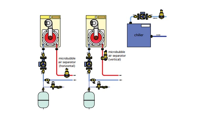
Air separators work best when located where the solubility of dissolved gases within the system water is lowest. Higher temperature and lower pressure conditions are best for removing the air from the fluid. In heating systems, the air separator should be mounted near the outlet of the heat source (see Figure 2). In cooling systems, they should be mounted on the inlet side of the chiller (e.g., where water temperatures are warmer).

The amount of air that can remain dissolved in a water solution is a function of pressure and temperature. This relationship is governed by Henry’s Law. The graph below demonstrates the physical phenomenon of the air release from water. As an example, at a constant absolute pressure of 30 psi (2 bar), if the water is heated from 65° F (18° C) to 170° F (75° C), the amount of air released by the solution is equal to 1.8 gallons of air per 100 gallons of water. According to this law, it can be seen that the amount of air released increases with temperature rise and pressure reduction. The air is present in the form of microbubbles of diameters in the order of tenths of a millimeter.

Priority No. 2: Removing dirt
Two types of debris can exist within a hydronic system. Both are problematic.
Ferrous debris forms in systems when iron or steel corrodes. Magnetite, a.k.a. “boiler ink,” is an abrasive, highly magnetic and extremely fine sediment that is difficult to remove. It can cause damage to rotating components in circulators, especially impeller and bushing surfaces. Figure 4 shows two examples of circulators with clogged impellers caused by debris and iron oxides within hydronic systems.

Non-ferrous debris can enter a hydronic system in several ways. The most common is through repeated handling of piping and system components from manufacturing through transportation and installation. Piping and components stored on-site can accumulate wind-blown dust or even larger dirt particles if dragged over the ground or dirty floor surfaces. Insects can nest in piping stored in warehouses or on job sites. Installers can leave pipe tape, copper shavings and solder residue behind if not careful.
A magnetic filter alone will not solve the problem. Unless air, ferrous debris and non-ferrous debris are removed from the system, the symptoms will continue to persist.


Because most dirt particles have a density greater than water, they tend to migrate toward the lower portions of the system. Thus, it makes sense to separate and capture them in this area. It also makes sense to continually route system flow through a dirt separator to increase the number of passes the system volume makes through the device in a given amount of time.
Dirt separators are commonly placed on the inlet side of boilers, heat exchangers and other heat sources, as shown in Figure 6. This is especially important in systems using boilers or other heat sources with compact heat exchangers. It’s also very important in systems where a new boiler is installed in a system containing older piping and/or cast iron radiators, as shown in Figure 7.

The gold standard solution
First, keep the dissolved oxygen concentration below the level that can cause reactions with ferrous materials. Second, protect the boiler (or chiller) with a magnetic dirt separator that collects not only ferrous but non-ferrous debris. Problematic non-ferrous debris includes copper shavings, pipe tape, pipe sealant and solder. Piping and other equipment stored outside can collect dirt, silica, dust and insects. Calcium scale that forms and breaks off within a system is also non-ferrous. All of these non-ferrous debris types are not captured by a magnet.
Photos courtesy of Caleffi North America.
Looking for a reprint of this article?
From high-res PDFs to custom plaques, order your copy today!


