John Siegenthaler: Geothermal pipe passages
Bringing earth loop piping through poured concrete.

Image courtesy of KangeStudio / iStock / Getty Images Plus
Water-to-water heat pumps, supplied from geothermal earth loops, represent a growing sector of the hydronic heat source market. Most current-generation models can produce water temperatures up to about 125° F, perhaps a little higher if you’re willing to push the compressor operating envelope. That temperature is very “workable” for a variety of heat emitters, including several types of radiant floor, wall and ceiling panels, and properly sized panel radiators or fan coils.
Water-to-water heat pumps can also produce chilled water in a typical temperature range of 45-55° F for cooling. That opens up many opportunities for a single installer to provide a “total hydronic solution” for space heating, domestic water heating and cooling.
Details matter
There are plenty of manuals and software programs available to help designers size earth loop piping depending on the capacity of the heat pump, location, soil characteristics and other factors. However, in my experience, there’s a lack of installation details that can help to put a final “polish” on projects.
For example, what’s the best way to bring earth loop piping through a typical poured concrete basement wall in a manner that provides a long-lasting water-tight seal?
One method that I’ve seen, but not impressed with, is core drilling a hole slightly larger in diameter than the piping, shoving the piping through it, and then emptying multiple tubes of caulk into the annular space between the pipe and hole. The quality of the seal produced in this manner is marginal, and subject to expansion and contraction forces that, over time, can cause cracks and subsequent leaks, especially when the soil against the wall is saturated by heavy rain.
A similar situation occurs in systems where piping from an outdoor wood-fired heater, or pellet boiler in a separate building, needs to pass through a poured concrete foundation wall.
Doing it right
One technique that I’ve found works well in these situations is to use a segmented “donut seal” device that’s specifically sized for both the diameter of the hole in the concrete wall, and the pipe passing through that hole. One example of such a product that has good brand recognition is a “Link-Seal,” and example of which is shown in Figure 1.
 FIGURE 1 Image courtesy of Garlock Products
The concept for this device is simple, and, in my opinion, brilliant. Several curved segments of pliable rubber (EPDM, Nitrile or Silicone) are held in place between small pressure plates made of reinforced nylon polymer or metal. Several stainless steel bolts pass through these plates and the rubber segments. When the bolts are tightened, the plates squeeze the rubber segments outward as well as inward. A seal is created against both the concrete surface and the outer surface of the pipe. That seal can resist pressures up to 20 psi, which, if ever allowed to occur, would likely cave in plenty of poured concrete walls. Suffice it to say, this seal is more than adequate for any reasonable pressure that could occur on typical residential basement walls.
If the pipe ever has to be moved, which is unlikely for geothermal loop applications, the bolts can be loosened and then retightened. No caulk, no mess and fast installation.
Making the hole
The traditional method of creating a hole of a specific diameter larger than perhaps 1 inch and through an existing concrete wall is to set up a core drill. For those that have never done this, it’s not as simple as boring a hole in a 2x4. Most contractors that aren’t boring such holes on a frequent basis will need to rent the core drill, and also pay for the wear on the diamond end of the bit. Then it’s a matter of bracing the drill to allow pressure against the wall and providing a hose for continuous water flow during the bore. In short, it’s a messy, noisy and often expensive operation. Still, when the wall exists, it’s just about the only option.
However, in cases where the wall hasn’t yet been formed or poured there’s an alternative that I’ve found works well.
Order some solid polyethylene “rods” on eBay, or another source. You can find them in a range diameters and lengths. Some suppliers will even cut to your length requirement, which would be the same as the thickness of the wall. These rods will serve as “blanks” in the formwork. They simply occupy space that otherwise would fill up with concrete.
Figure out where you want the holes in the wall, hold the flat side of each rod in that position and have some put a couple of deck screws through the outer form into the end of the rods, as shown in Figure 2.
 FIGURE 2
Keep track of the measurements, and put two more screws through the inner form into the end of each rod.
Spray some release oil on the rods just before the pour to ensure there won't be a bond.
The concrete should be placed in the forms gently and vibrated to ensure it totally surrounds each rod.
When it’s time to strip the forms just back out the screws, pull the forms and gently tap on the end of each rod with a hammer. Each rod will slide out of the wall like a piston moving out of a cylinder. You’ll be left with smooth and accurately sized holes ready for the piping and the “donut seal,” as shown in Figure 3.
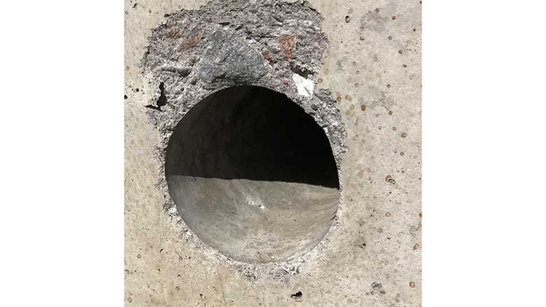 FIGURE 3
Figure 4 shows a 1-inch DR-11 HDPE pipe passing through a Link-Seal that fits into a 3-inch diameter hole through the concrete wall.
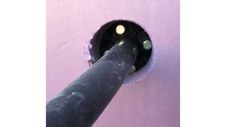 FIGURE 4
When the 4 bolts on this seal are snugged up the seal is made. A layer of 2-inch extruded polystyrene has been placed against the inside of the wall.
Figure 5 shows progress on the job. Each of the eight 1-inch HDPE pipe penetrations transitions to a 1.25-inch copper header system.
 FIGURE 5
The ball valves on the supply and return of the 4 earth loop circuits allow for easy (one loop at a time) filling and purging. They also allow the possibility — although very unlikely — of isolating each circuit from the balance of the system if necessary.
Keeping it inside
I like this approach for bringing multiple earth loop circuits into a common supply and return to the heat pump. In this system, each of the 4 earth loop circuits were taken from 1,000-foot coils of 1-inch DR-11 HDPE. There was no need for fusion joints in exterior piping. All the joints are inside and readily accessible.
The final step is to completely insulate the piping to prevent condensation. Figure 6 shows the installation where the piping has been insulated. The air/dirt separator, as well as the circulator volute, still need to be insulated with some carefully fitted sheets or taps of elastomeric foam.
 FIGURE 6
Notice that the earth loop system includes an expansion tank and an air/dirt separator. I recommend these for all earth loop systems, which, after all, are just another type of closed-loop hydronic circuit. The fill and purging valves are located on the right side of each header.
To date, the earth loop system we’ve discussed has been operating very well. It maintains a stable pressure year-round, and has not needed any purging or other adjustments after its commissioning.
Maybe you can use some of the details shown above in one of your upcoming geothermal projects.
Wishing you and your family a joyous and blessed Christmas.
Looking for a reprint of this article?
From high-res PDFs to custom plaques, order your copy today!


