The Glitch & The Fix: Radiator Redo

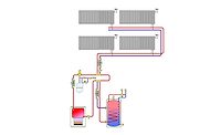
Figure 1: The glitch
The Glitch:
An installer is asked to assess a system in which an aging steam boiler supplies several cast-iron radiators. After inspecting the radiators, he proposes to convert the system from steam to hot water and replace the old boiler with a mod/con boiler. The installer pipes in the new boiler to the existing black iron piping system as shown in Figure 1, and installs thermostatic radiator valves (TRV) on each radiator to provide room-by-room zone control. The circulator is wired to run continuously during the heating season. Although the installer’s intentions are good, can you spot some potential problems with the make-over and suggest some improvements?
The problems:
One of the problems with the proposed piping layout is the circulator placement. It’s pumping toward the connection point of the expansion tank. This results in a drop in pressure between that point and the inlet of the circulator. It may even be possible that the pressure in this portion of the system goes sub-atmospheric when the circulator is operating. That’s an invitation for air to enter the system.
Another issue involved where the thermostatic radiator valves were installed. In the position they are shown in Figure 1, the TRVs would be heated by convection and radiation from their associated radiator. This would cause them to “short cycle” (e.g., the valves would shut off very shortly after they begin allowing heat to be released from the radiator). The TRVs are also installed backward. Flow should always pass upward through the valve’s seat. Most TRVs are intended to be installed on the inlet side of heat emitters, and have a flow direction arrow on the valve body.
Flow through the new boiler would be dependent on the status of the TRVs if they were all closed the circulator would be deadheaded. If only one was open, the flow through the boiler would likely be much lower than intended by the manufacturer. This would create mechanical stress that’s likely to shorten the boiler’s life.
Old steam systems are likely to have accumulated sludge formed by oxidation of the iron pipe and radiators. Mod/con boilers with compact heat exchangers do not take kindly to that sludge. The output and efficiency will quickly degrade as the sludge accumulates on the interior surfaces of the boiler’s heat exchanger.
There’s also no provision for efficient purging of the system.
The Fixes
Figure 2 shows one way to modify the system to correct these issues.
Figure 2

A hydraulic separator equipped with a strong internal magnet provide several functions:
- It allows the boiler flow to remain consistent regardless of the flow through the distribution system;
- It provide microbubble air separation;
- The lower chamber of the separator, in combination with the magnet collects sludge that could otherwise clog the boiler’s heat exchanger. The accumulated sludge is periodically flushed from the valve at the bottom of the separator; and
- It allows for constant operation of a variable-speed pressure-related circulator in the distribution system. This type of circulator is well suited to systems sign valve-based zoning. It ramps flow rate up and down as the different TRVs open, close, or modulate. If all TRVs happen to be closed, the circulator goes into a low power “sleep” mode. it reawakens as soon a one of the TRVs begins to open.
The TRVs shown in Figure 2 have angle pattern bodies. This keeps the thermostatic head far enough from the radiator to minimize convective interference that could cause erratic operation of the valve. They are also installed on the inlet side of the radiators.
Manually-operated air vents are shown at the top of each radiator to aid in purging the system.
A purging valve has been installed on the inlet of the hydraulic separator to allow for adequate forced water purging of the distribution system, and initial dirt removal. Another purging valve has been added on the outlet piping from the boiler to ensure that the boiler circuit can be properly flushed of air during commissioning. This valve, in combination with the isolation flanges on the boiler circulator, allows the boiler to be isolated and drained if ever necessary.
The boiler can be enabled to operate based on a setpoint for outdoor temperature. For example, the boiler can be enabled to fire if the outdoor temperature drops below 50° F, and remains enabled until the outdoor temperature climbs above 60° F.
Once the components are installed this system should be flushed with a hydronic detergent to internally clean the old piping components and radiators.
A supply temperature sensor that regulates boiler modulation is shown on the supply side of the distribution system (downstream of the hydraulic separator). This allows the boiler to modulate based on the true water supply temperature to the radiators. It’s often possible to operate this type of system using the outdoor reset control logic present in most mod/con boilers.
Looking for a reprint of this article?
From high-res PDFs to custom plaques, order your copy today!


