The Glitch & The Fix
Concrete slab over radiant tubing — who takes the blame?

Images courtesy of John Siegenthaler.
The Glitch:
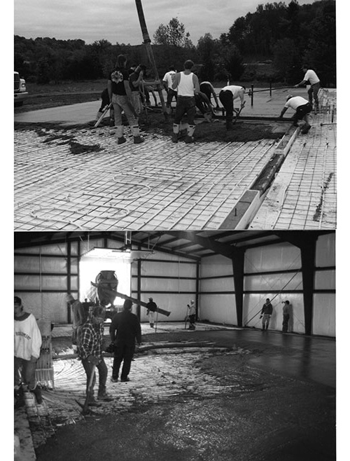
Take a look at the two photos in Figure 1. They both show the placement of a 6-inch thick concrete slab containing 5/8” PEX tubing at 12-inch spacing. The tubing is fastened to 6x6 welded wire reinforcing. Do you see any installation practices that might compromise the eventual structural or thermal performance of this slab?
FIGURE 1
The Fix:
In both of these projects, the masons are dumping and leveling the concrete on top of the tubing and welded wire reinforcing (WWR), but making no attempt to lift the WWR or attached tubing above the bottom of the slab.
Perhaps they think that the WWR is only there to hold the tubing in place during the pour. That’s what a contractor actually told me on a project I designed several years ago. It makes me wonder what they do when pouring a slab that doesn’t contain tubing. Do they understand what the WWR is for and where it should be within the slab? I suspect the answer is: “I sorta know, but really don’t care.”
The guideline specifications from the Wire Reinforcing Institute call for a single layer of welded wire reinforcing (WWR) to be installed between 1/3 and 1/2 the depth of the slab, measured down from the slab surface. Leaving the (WWR) at the bottom of the slab does not allow proper “engagement” with the concrete, and provides little, if any, resistance to shrinkage cracking, which is usually the intended function of (WWR). Thus, even in non-heated slabs, the WWR should be lifted or otherwise supported so that it is embedded at the proper depth within the slab.
Beyond structural performance are the heat transfer implications. Figure 2 shows the variation in upward heat output from a 4” thick bare concrete slab based on tubing spaced 12” apart, installed at two depths, and operating at an average water temperature of 100° F.
FIGURE 2
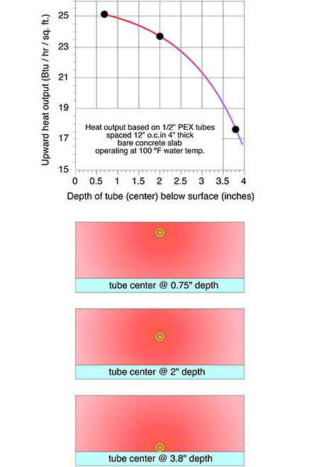
In theory, there’s a 26% drop in heat output for tubing installed at the bottom, rather than the mid-height of the slab — when both are operated at the same water temperature.
If the slab needs to release heat at a rate of 15 Btu/h/ft2, the average circuit water temperature needs to increase about 7° F if the tubing is left at the bottom of the slab rather than placed approximately at mid-slab thickness.
If the slab needs to release heat at 30 Btu/h/ft2, the average circuit water temperature needs to increase 15° F. These temperature increases will lower the thermal efficiency of modern heat sources such as condensing boilers and especially heat pumps.
Leaving tubing at the bottom of the slab also increases downward heat loss, and significantly lengthens the slab’s response time to changes in water temperature. The latter can lead to pronounced temperature overshoot, especially if there are significant and unpredictable internal heat gains from the sun, people, or equipment.
The bottom line is simple: The depth of the tubing within a heated slab does make a significant difference in performance. When the tubing is tied to WWR, both the WWR and tubing should be placed at approximately half slab depth.
Why compromise the structure and thermal performance of a heated slab based on careless workmanship? Make sure your written specifications and construction drawings show and describe how to do it right.
If the masons or the GC disagree, perhaps you can show them Figure 2. If they still disagree, perhaps they would be willing to sign a release stating that they, not you, are now responsible for the performance of the slab.
What do you think the chances of that are?
Looking for a reprint of this article?
From high-res PDFs to custom plaques, order your copy today!


