Hydronics Workshop | John Siegenthaler
Do you understand hydraulic separation?
A simple but powerful design tool.
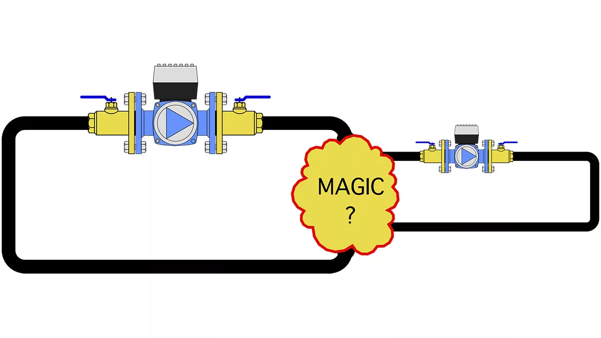
Image courtesy of John_Brueske / iStock / Getty Images Plus.
Many technologies have their “glory days.” Times when technical improvements happen quickly, performance gains are impressive, and interest is strong.
In my opinion, the 1940s through the 1990s were the glory days of aviation. Huge progress was made, starting with the propeller-driven fighters that helped win World War 2 and extending through research jets that could fly six times the speed of sound just three decades later. A lot of kids — including me — wanted to be a pilot and strap themselves into one of those incredible machines.
Although less glamorous than aviation, North American hydronic technology also had its glory days. In my experience, this period began in the mid-1980s when PEX tubing made its way here from Europe. Prior to PEX, residential hydronic heating was mostly two or three of zones of fin-tube baseboard supplied from a cast iron boiler. These systems worked, but they weren’t very “sexy.” In those days, there weren’t many homeowners who wanted to give their guests tours of their boiler rooms.
So what changed?
The availability of PEX tubing led to a revival of interest in radiant panel heating. Although there were plenty of early mistakes — like stapling PEX to the side of floor joists and expecting it to heat the space above — progress was made.
Soon designers were looking for ways to expand systems beyond just radiant panel heating. They wanted to incorporate multiple boilers, higher temperature emitters along with low-temperature radiant panels and domestic water heating into the same system. Houses were growing in size and adding “thermal amenities," such as snow-melting and pool heating. The multi-load systems designed for these projects usually included several circulators, often of different sizes and performance, and in many cases, two or more of those circulators operated simultaneously.
This led to an increase in problems that could be summarized as the big circulators “bullying” the small circulators. There were large shifts in flow rates, depending on which circulators were operating at any time. I even witnessed one system where interference from a large circulator completely stopped flow in a circuit powered by a smaller circulator, even with the latter running on its highest speed setting.
While trying to solve these problems, the North American market eventually rediscovered a technique that had its roots back in the 1960s: Primary/secondary piping. Coupling one circuit to another using a pair of closely-spaced tees all but eliminated any interference between the circulators in the two circuits. Designers, including myself, began churning out schematics where multiple secondary circuits, each serving a different load, were coupled to a primary loop using pairs of closely spaced tees.
For the most part, these designs worked, and the technique grew in popularity. Still, I’m convinced that a significant percentage of designers or installers don’t fully understand why closely-spaced tees do what they do. They just install the tees as shown on plans and wait for the “magic” to happen.
It’s all about the common piping
Primary/secondary piping is one of several ways to achieve hydraulic separation. It’s one way to couple two or more overlapping hydronic circuits, each with its own circulator, so that the circulators don’t interfere with each other. If you understand the underlying principle of hydraulic separation, you’ll understand why a pair of closely spaced tees is one way to achieve it.
Consider the hypothetical piping system shown in Figure 1:
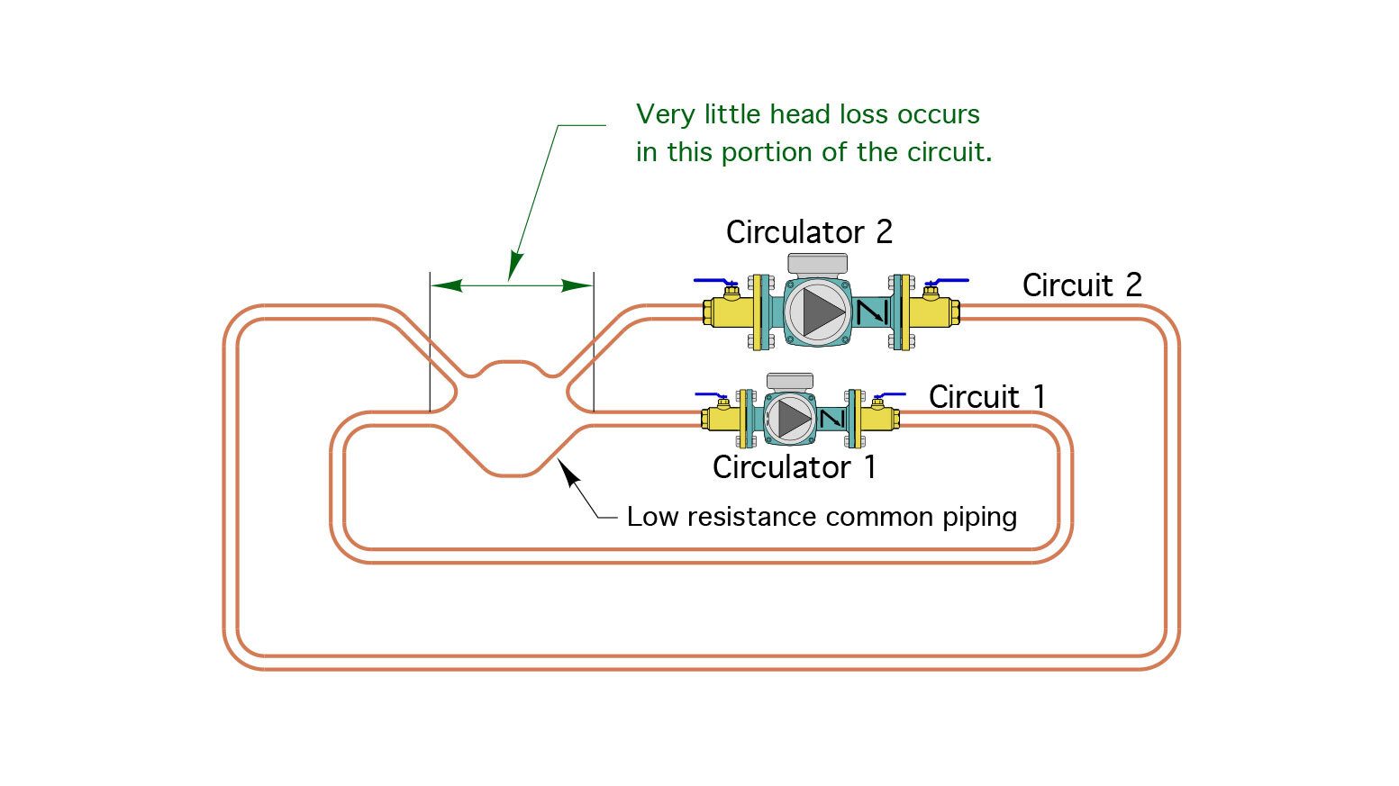
FIGURE 1
This system consists of two parallel circuits, each with its own circulator. Assume that the circuits can have different pipe sizes, pipe lengths, fittings, etc. The circulators are also different in size.
The two circuits “overlap” at the “bulge” to the left of the circulators. We can call this bulge the common piping because it is shared by each circuit.
Because it has a wide cross section, and its length is relatively short in comparison to the lengths of each circuit, the head loss across the common piping will be very small.
Start by assuming that circulator #1 is running, and circulator #2 is off. Figure 2 shows the pump curve of circulator #1, along with the head loss curve for circuit #1. That head loss curve includes the head loss of the piping in circuit #1, and the very small head loss across the common piping.
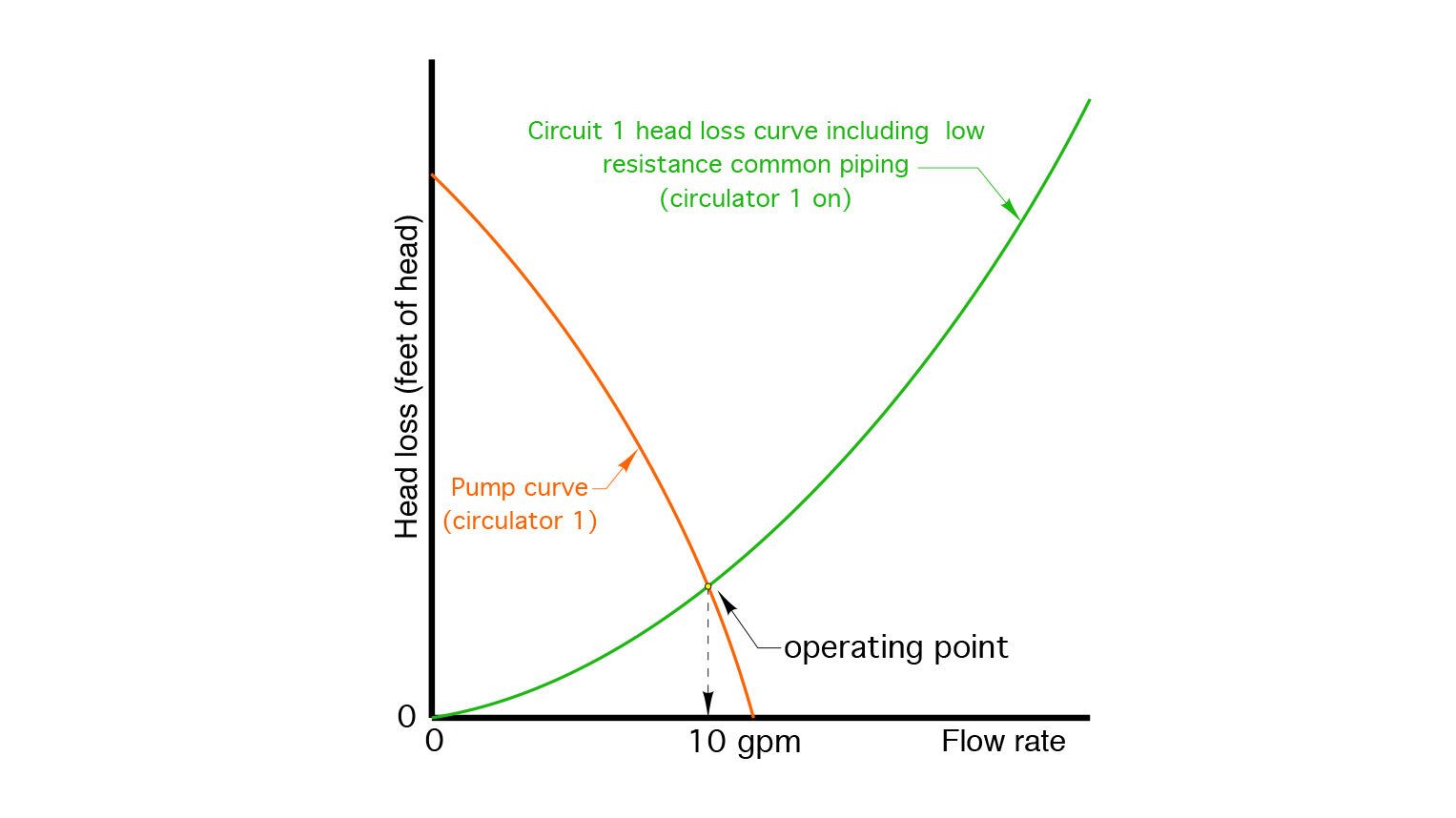
FIGURE 2
The operating point — where the pump curve crosses the head loss curve — corresponds to a flow rate of 10 gpm.
Next, assume that circulator #2 is turned on and circulator #1 remains on. The total flow of both circuits now passes through the common piping. This will cause a slightly higher head loss across the common piping, which will slightly increase the total head loss of circuit #1. The change is represented by the blue curve in Figure 3. For comparison, the original (green) head loss curve for circuit #1 is also shown.
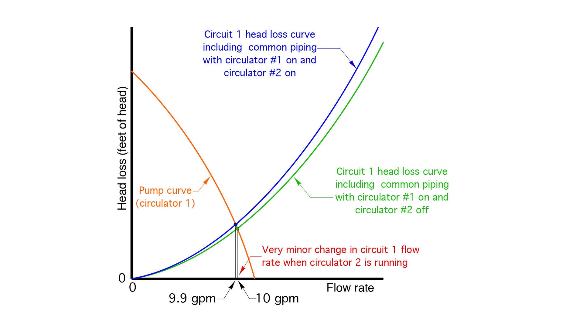
FIGURE 3
Notice that the operating point moved very slightly to the left, from the (green) dot to the (blue) dot. This slight change causes the flow rate in circuit #1 to drop from 10 gpm to 9.9 gpm. That change, for all practical purposes, is of no consequence. Thus we can consider the two circulators in this system to be hydraulically separated from each other. This desirable effect is a result of the two circuits “sharing” common piping that has very small head loss.
Imagine this
Another way to think about two circuits that are hydraulically separated is to imagine each circuit as being physically separate from the other, as shown in Figure 4.
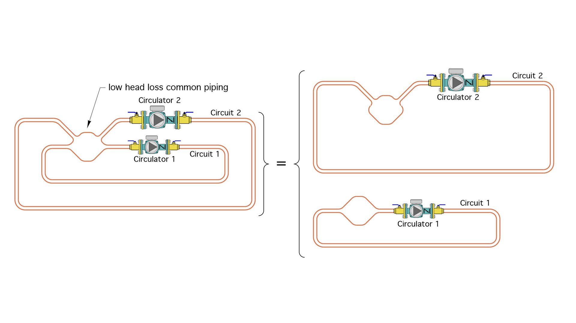
FIGURE 4
The flow rates that would be established by each circulator in its associated sub-circuit (such as 10 gpm in circuit #1, and 12 gpm in circuit #2) would be approximately the same regardless of the two circuits “overlapping” as shown on the left, or completely isolated from each other, as shown on the right.
So here’s the takeaway:
Anything that couples together two or more hydronic circuits, each with its own circulator, and where the head loss of the coupling method is very small, results in hydraulic separation of the circulators.
There are several hardware configurations that meet this criteria:
- A pair of closely-spaced tees (classic primary/secondary piping);
- A buffer tank piped as either a 2-pipe, 3-pipe, or 4-pipe configuration;
- A typical cast iron boiler combined with short/fat headers; and
- A hydraulic separator combined with short/fat headers.
These hardware configurations are illustrated in Figure 5:
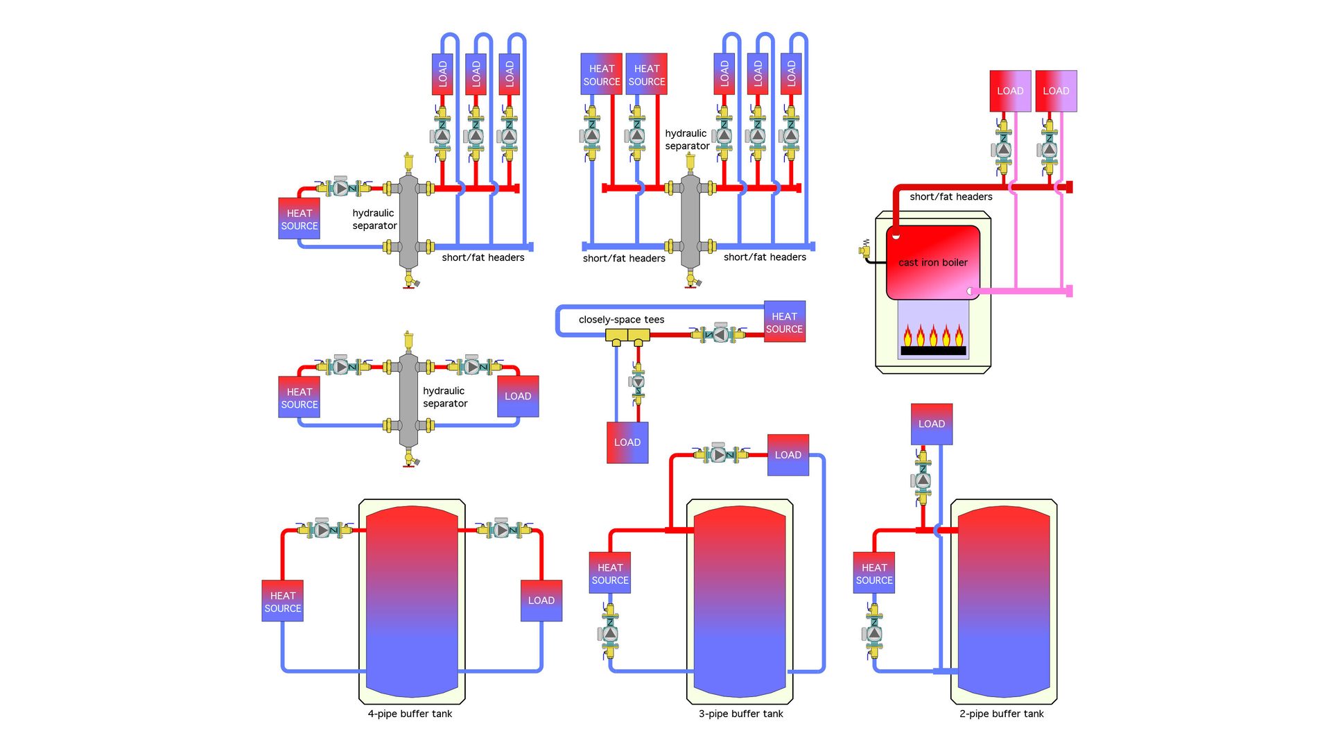
FIGURE 5
All of these arrangements bring together two or more circuits, each with their own circulator, in a way that creates very little head loss where the two circuit overlap.
For the closely spaced tees, this overlap is a tube stub just long enough to join the tees side by side.
For systems with buffer tanks piped as shown in Figure 5, the buffer tank is the low head loss common piping. The large cross-sectional area of the tank produces very low flow velocities inside the tank, and thus very low head loss.
The cast iron boiler consists of several sections that each have large cross-sectional areas, and thus create very low flow velocity and head loss. Still, it’s important to use what I call “short/fat headers” to preserve the hydraulic separation effect of the cast iron sections up to the point where the circulators connect to the system.
Then there’s a hydraulic separator. The cross-sectional area of the vertical portion of the separator is about nine times larger than the cross-section of the piping connected to it. This reduces flow velocity to about 1/9 that in the piping, which again results in very low head loss.
The nice thing about a hydraulic separator is that it also can provide efficient air and dirt separation for the system. To “preserve” the hydraulic separation it’s also important to use short/fat headers on both sides of the separator.
Another benefit of a hydraulic separator, relative to a classic series loop in a primary/secondary piping system, is that each parallel load circuit receives the same supply water temperature.
Multiple points of separation
Combinations of the details shown in Figure 5 can also be used in the same system. One example of such a combination is shown in Figure 6.
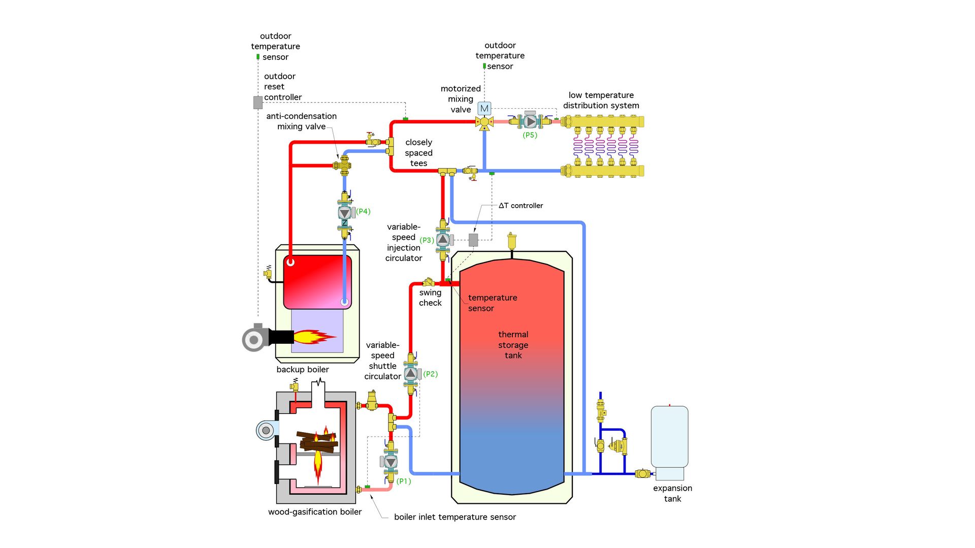
FIGURE 6
In this system, the fixed speed circulator (P1) providing flow through the wood gasification boiler is coupled to a variable speed shuttle circulator (P2) using a pair of closely spaced tees. This decoupling allows (P2) to adjust speed as necessary to maintain the boiler inlet temperature high enough to prevent sustained flue gas condensation.
The thermal storage tank provides hydraulic separation between variable speed circulators (P2) and (P3). Note that the piping circuits containing these two circulators tee together very close to the tank. This minimizes head loss in the short headers that connect the tees to the tank.
The variable speed injection circulator (P3) is hydraulically separated from the oil-fired boiler circulator (P4), and the distribution circulator (P5) by two more sets of closely spaced tees.
This system has five circulators and four points of hydraulic separation. Although the overall schematic may look complicated, think of it as broken up into 5 subsystems, as shown in Figure 7.
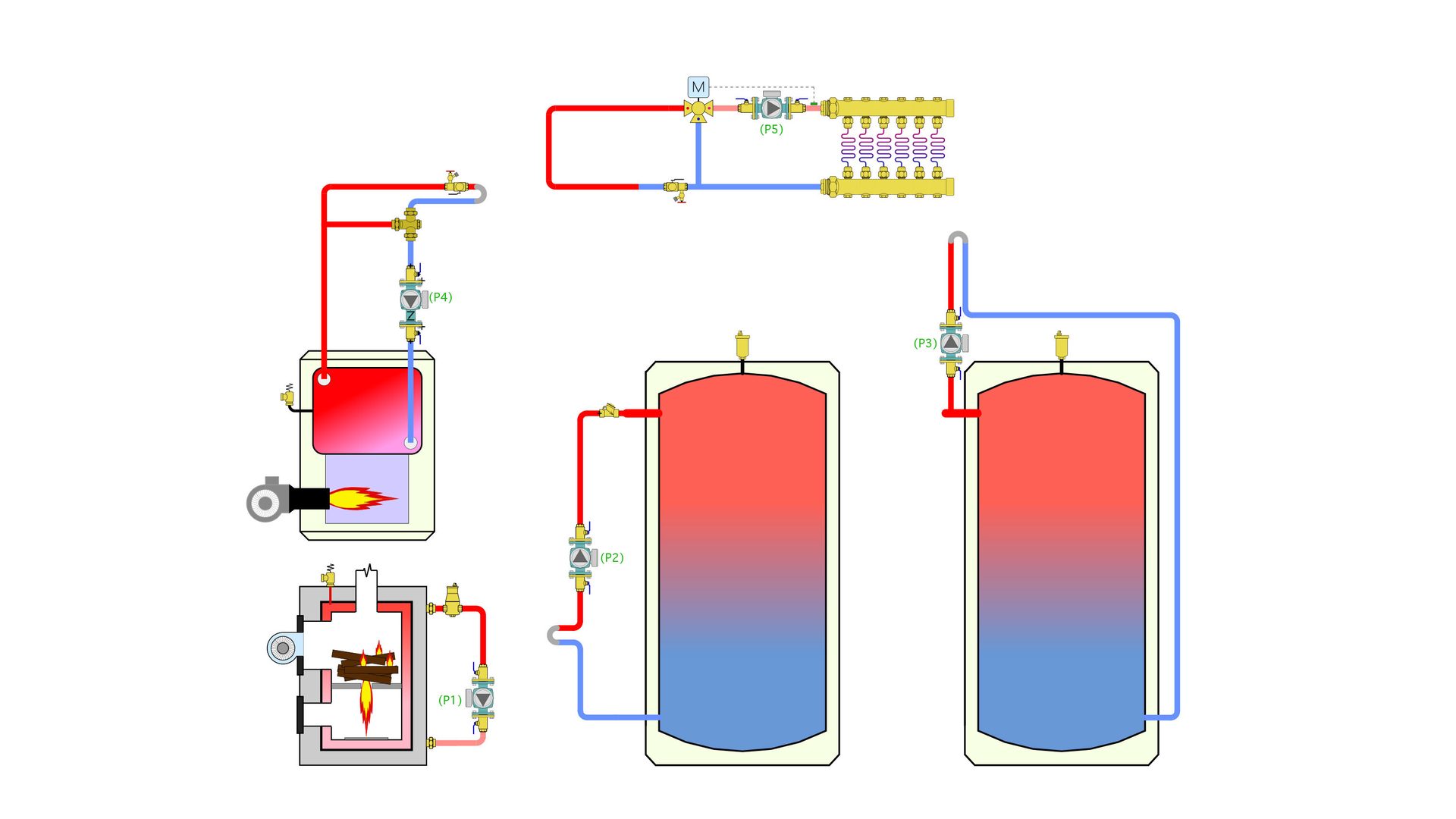
FIGURE 7
The flow rate established in each of these subsystems is essentially unaffected by flow rates in the other four subsystems. That may be hard to believe when looking at the overall system, but it’s true.
The bottom line
There’s no “magic” involved with hydraulic separation. Anything that couples two or more circuits together so that the piping they share has very low flow resistance can provide it. In this context, it’s a really simple concept, but also one that’s extremely useful in hydronic system design.
By the way… I don’t think the “glory days” of modern hydronics technology have ended. The opportunities at hand for creative designers continue to expand. Water is still the best stuff on earth for moving thermal energy around. Just make sure your designs respect the concept of hydraulic separation to “keep the peace” between potentially competing circulators.
Looking for a reprint of this article?
From high-res PDFs to custom plaques, order your copy today!


