Geothermal heat pump systems with manifolded earth loops offer advantages
Coming together.

Image Source: BanksPhotos / iStock / Getty Images Plus
Most residential and light commercial geothermal heat pump systems use closed-earth heat exchangers constructed of HDPE (high-density polyethylene) tubing. The overall earth heat exchanger typically consists of several parallel piping circuits that are joined into a set of headers.
In systems using horizontal earth heat exchangers, the header system is usually fabricated in the trench, and the entire piping assembly is buried several feet below the surface. Figure 1 shows an example where six “slinky” style earth loop circuits have been joined to reverse return headers (seen near the bottom center of the photo).
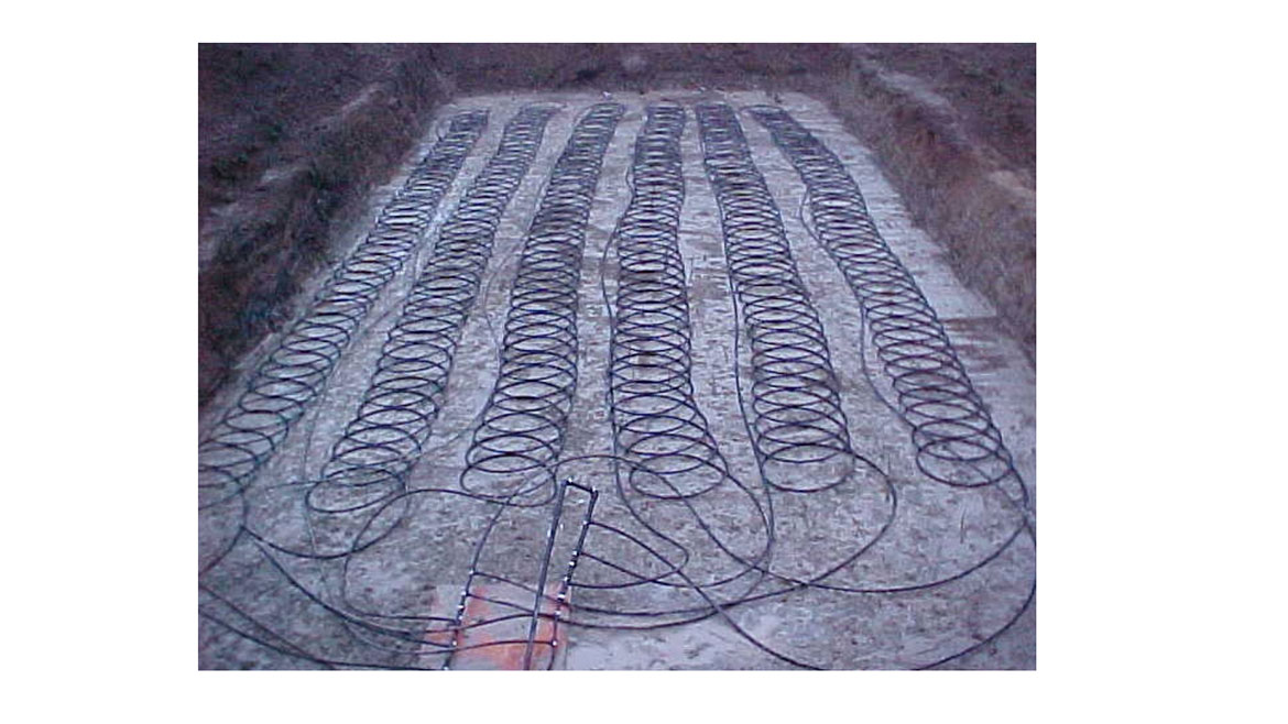
Figure 1 Image courtesy of Larry Wurtak
Figure 2 shows another example of individual earth loop circuits connected to headers in the trench. You can see it’s not an ideal working environment.

Figure 2 Image courtesy of Stage 3 Renewables
In systems using vertical earth heat exchangers, individual earth loop circuits are inserted and grouted into boreholes. These circuits are then joined into a common set of headers as shown in Figure 3. The headers are configured for reverse return flow and have incrementally stepped pipe sizes between the individual circuit connection tees. These details help equalize flow rates among the individual circuits — assuming the individual earth loop circuits are the same length.
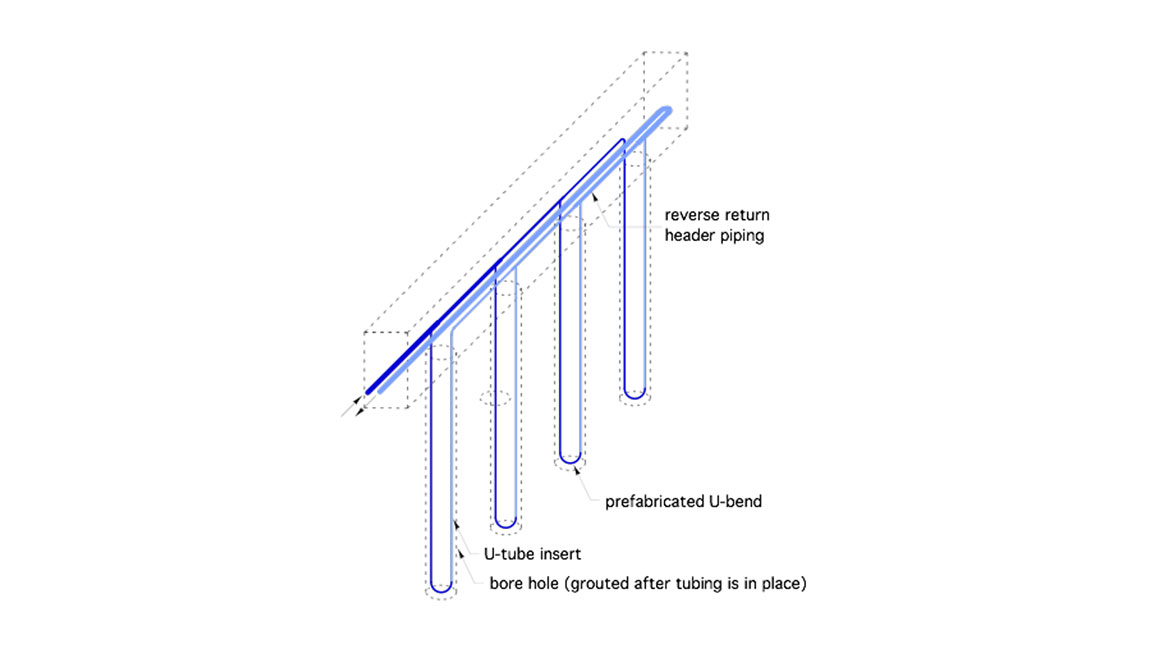
Figure 3. Vertical earth loop. Image courtesy of John Siegenthaler
The two most widely accepted methods of joining HPDE pipe for geothermal earth loops are butt fusion and socket fusion. Both methods involve heating the HDPE pipe to approximately 500° F, and then bringing the molten ends of the pipes or fitting together to form true molecular bonds. When properly executed, both types of fusion joints are stronger than the pipe itself. Both types of fusion joining also require specialized equipment and reasonable training. Contractors specializing in geothermal heat pump systems invest in that equipment, which can run into several thousand dollars. However, HVAC contractors who don’t specialize in geothermal systems usually don’t make this investment. Instead, they usually subcontract the earth loop work.
Although “trench-based” earth heat exchanger fabrication using fusion joining has been successfully used on thousands of installations, it does, at times, have to be performed under less than ideal conditions. Working with fusion equipment under cold, wet and muddy conditions requires special care to ensure the joints being made are clean, dry and properly heated.
This looks familiar
So what are the alternatives to fusion joints, and site-fabricated/buried headers?
One option that is commonly used in Europe for residential systems is the geothermal manifold. In some respects, this approach is similar to routing multiple radiant panel heating circuits to a common manifold station. However, geothermal manifolds are larger in diameter to accommodate higher flow rates. Most are built of polymer materials that can easily withstand the relatively low operating temperature and pressure range of earth loops.
One example is shown in Figure 4. In this case, the manifold body is built of polypropylene (PP-R) pipe. Individual circuits connect to the manifold body using heat-fused saddle tees.

Figure 4 Image courtesy of Legend Valve
A basic geothermal manifold would just provide connections for the individual earth loop circuits. However, the basic manifold can be “trimmed out” in several ways. For example, the manifold shown in Figure 4 has ball valves at each manifold connection, as well as an isolating ball valve for the manifold as a whole. It also has a tapping for an air vent.
Having ball valves for each circuit is particularly helpful when filling and purging the overall earth heat exchanger. It allows each circuit to be individually purged, which significantly reduces the flow rate needed to entrain air within the circuit and bring it back to a flushing assembly.
Some geothermal manifolds can also be equipped with flow meters to measure the flow rate in each circuit. The measured flow rate can be used in combination with temperature measurements at the beginning and end of each circuit to estimate the rate of heat transfer from each circuit.
It’s also possible to connect several geothermal earth loops using an interior site-built manifold constructed of copper tubing as shown in Figure 5.
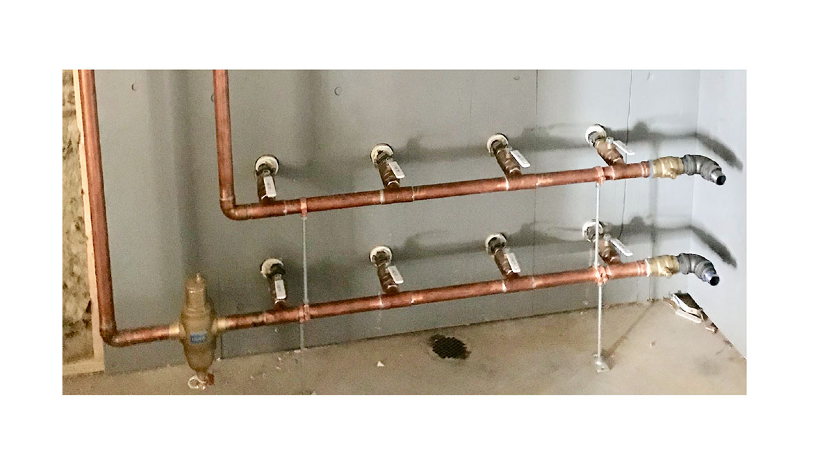
Figure 5 Image courtesy of John Siegenthaler
In this system, which serves a 4-ton water-to-water heat pump, the manifold is constructed of 1.25-inch copper with 1-inch copper side port tees. Treaded rods support the assembly. Each circuit is equipped with ball valves on supply and return. The transition to 1-inch HDPE DR-11 pipe is made using barbed connectors and double stainless steel worm-drive clamps. Each earth loop is approximately 1,000 feet long, with no exterior joints. Temporary fittings to accommodate filling and flushing are seen on the right side of the manifolds. The entire assembly was later covered with elastomeric foam insulation to prevent surface condensation when earth loop temperatures drop below room dewpoint, which is common in Northern locations.
Advantages of manifold-based earth loops
The use of manifold-based earth loops provides several advantages relative to earth loops created using buried fusion joints. These include:
- The possibility for installing several different earth loop configurations without need of fusion joints, and thus no need of fusion equipment. This is a significant advantage for contractors who do an occasional geothermal heat pump installation, but can’t justify buying all the tooling required for fusion joints.
When the manifold station includes isolation and flow indicating/balancing valves additional advantages include:
- Each circuit of the earth loop can be independently flushed during filling and purging. This significantly reduces the size of the flush pump required to fill and purge the system.
- The flow rate through each earth loop circuit can be verified.
- If a buried circuit ever fails due to future excavation, drilling, etc., it can be completely isolated at the manifold.
Inside or outside
Geothermal manifold stations can be located either inside or outside the building served by the heat pump.
Figure 6 illustrates how individual earth loop circuits can pass through a basement wall and connect to 90° compression elbows. The latter changes the direction of the piping from horizontal to vertical. The vertical piping then rises up to connect to supply and return manifolds.
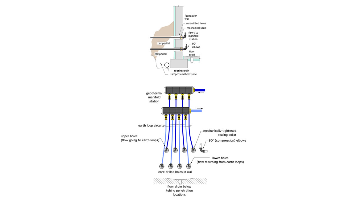
Figure 6 Image courtesy of John Siegenthaler
Several options exist for geothermal manifold stations located outside the building. One is to use a precast concrete vault. All piping penetrations through the vault walls must be watertight. If the top of the vault is below grade, it must also be sealed to the vault walls. The goal is to prevent entry of ground or surface water. Still, it’s prudent to include a water detection system at the floor of the vault, as well as an automatic sump pump to prevent flooding should any seal fail.
Figure 7 shows an example of a pre-cast concrete vault that houses two sets of supply and return manifolds for a large geothermal heat pump system. The larger pipes running through the near side of the vault are the supply and return between the manifolds and the balance of system. This vault will be capped with a pre-cast concrete cover, sealed to the walls. It will have an access panel just above final grade. There will be a permanent access ladder from the surface into the vault. Granular backfill materials must be carefully placed and compacted under the external piping to minimize settling.

Figure 7 Image courtesy of Advance Concrete Products
Figure 8 shows a smaller (residential scale) geothermal manifold vault, constructed of molded high-density polyethylene. All piping penetrations are fusion welded to maintain a watertight seal.
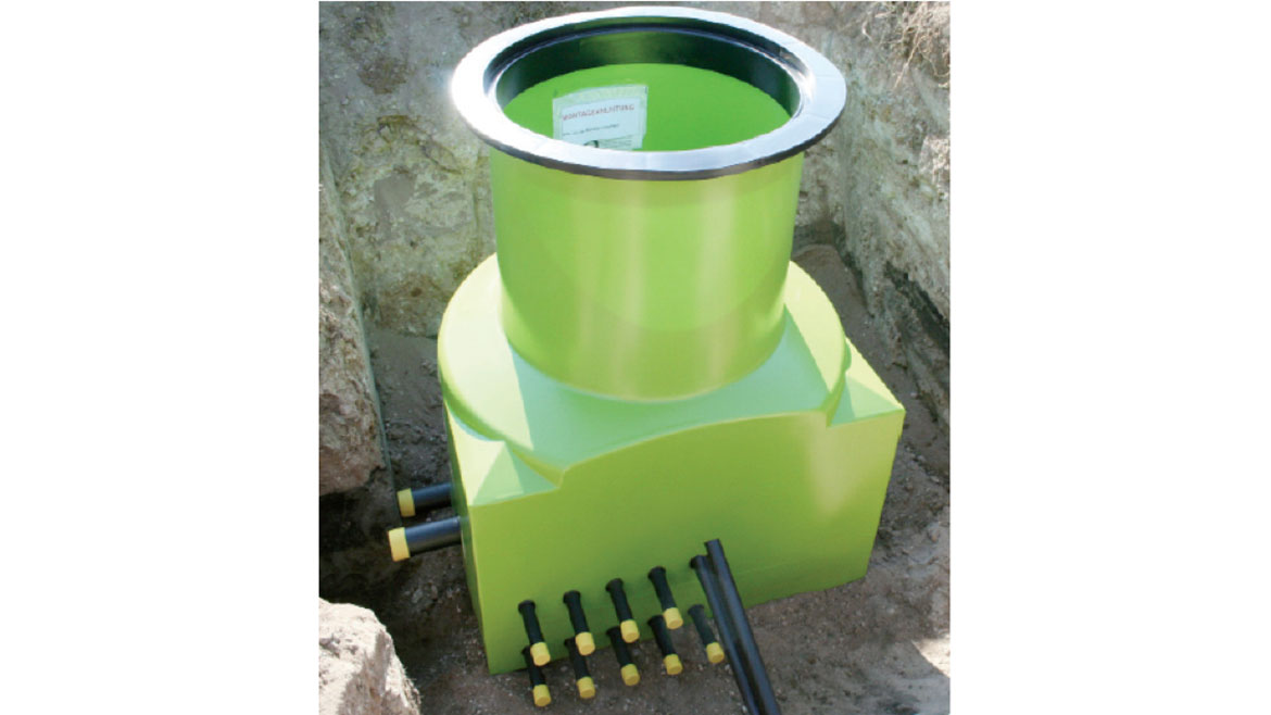
Figure 8 Image courtesy of REHAU
Significant difference
One of the biggest advantages of using valved manifold-based earth heat exchangers is the size of the pump required for filling and purging. That pump will be significantly smaller for a valved manifolded system because each earth parallel circuit can be flushed individually. Without valves, all the circuits must be flushed simultaneously.
Purging requires a minimum flow velocity of 2 feet per second in every tube that’s being purged at a given time. That flow velocity corresponds to a flow rate of 3.6 gpm in a 3/4-inch DR-11 HDPE tube, and 5.6 gpm in a 1-inch DR-11 HDPE tube.
Here’s a comparison of the flow rates and corresponding head losses required for purging a conventional earth loop versus one using a valved manifold.
Based on working through a few calculations, the non-valved earth loop circuit shown in Figure 9 requires a purging pump capable of producing a minimum flow rate of 28.5 gpm at a corresponding head of 72.6 feet. That’s a substantial pump, likely in the range of 1.5 to 2 horsepower. Such a pump may require a 240 VAC power supply.
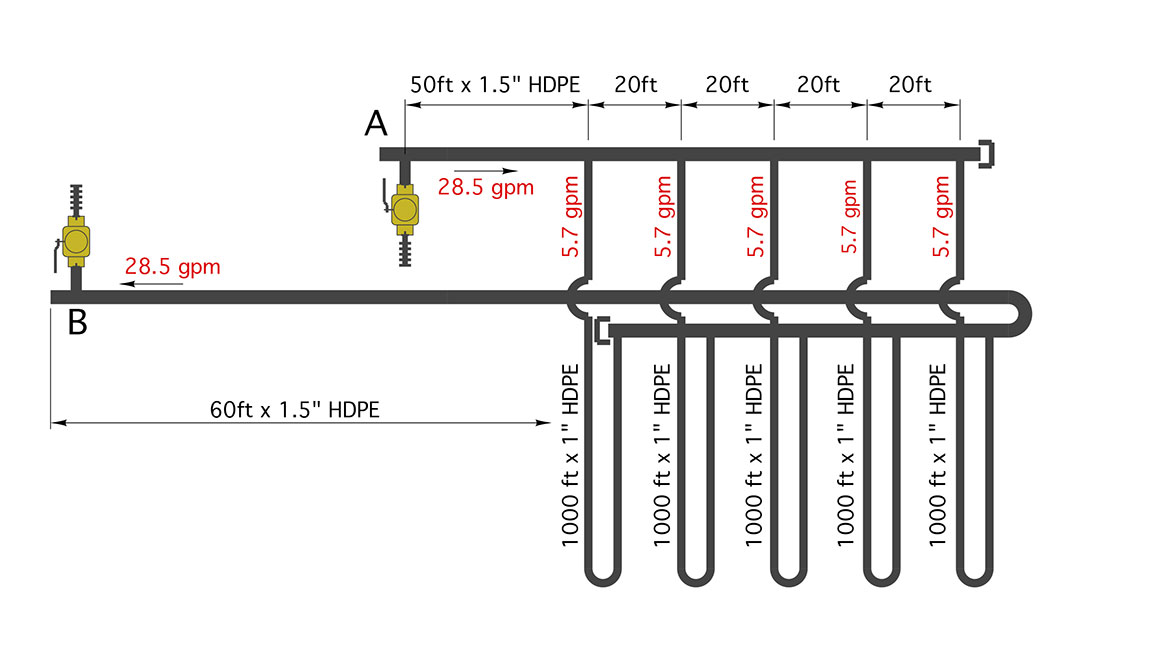
Figure 9 Image courtesy of John Siegenthaler
By comparison, if the same set of five 1,000-foot parallel piping circuits were connected to a valved manifold, and purged one at a time, the purging pump would only have to deliver a flow rate of 5.7 gpm with a corresponding head loss of 20.7 feet. This is within the performance range of a portable submersible pump that operates on 120 VAC.
If you’re involved with geothermal heat pumps, I urge you to consider the use of manifolded earth loops. They offer several unique benefits, not the least of which is less time in the trenches.
Looking for a reprint of this article?
From high-res PDFs to custom plaques, order your copy today!


