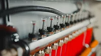
A sampling of low-temperature heat emitters


The reason is simple: Low water temperatures increase the thermal efficiency of just about any hydronic heat source. The one exception is an electric resistance boiler.
As Figure 1 shows, modulating/condensing boilers only can deliver their often-touted mid-90% thermal efficiency when the water temperature return from the distribution system is in the range of 100° F. The lower the inlet water temperature, the higher the boiler’s thermal efficiency.
The only way to maintain high efficiency operation under design load conditions is to use heat emitters that can deliver design output while operating at low water temperatures.
Most water-to-water geothermal heat pumps are limited to supply-water temperatures in the range of 120 to perhaps 125° F. There are some heat pumps that can deliver higher water temperatures through two-stage compression or other techniques, but their reduced coefficients of performance and heating capacity while operating at higher output water temperatures, and typical earth-loop temperatures, demonstrates this is a compromise. Figure 1 also shows the drop in COP as the water temperature entering the heat pump’s condenser increases.
Those working with solar thermal collectors quickly learn that operating them at low temperatures is the key to good efficiency and high overall energy capture. This also is demonstrated by the efficiency graph in Figure 1.
Even biomass boilers burning wood pellets or chips benefit from being coupled to low-temperature distribution systems — not because they can’t deliver water temperatures in the range of 180 to 200° F, but because they are almost always used in combination with thermal storage. The preferred operating mode of these boilers is to keep them running for several hours and sink any excess heat produced into storage. This improves the boiler’s thermal efficiency and reduces its emissions. The load then draws from thermal storage – hopefully for several hours – before the biomass boiler has to restart.
The lower the useable temperature of the thermal storage tank, the longer the boiler can remain off and the longer it can operate when restarted. Combining these boilers with low-temperature heat emitters helps drain the thermal storage tank to the lowest useable temperature before the boiler is called upon for the next “charging cycle.”
Abundant possibilities
Without a doubt, the most widely recognized low-temperature hydronic heat emitter is a radiant floor panel. There currently are many options for such panels, ranging from the familiar heated concrete slab, to low-mass panels using aluminum or graphite “fins” to conduct heat away from tubing and spread it out under the floor surface.
Hydronic radiant panels that use tubing embedded in floors, walls and ceilings are excellent in many applications. However, they don’t lend themselves to every possible scenario, especially in retrofit situations.
Throughout the last few years, several other low-temperature heat emitter options have entered in the North American market. I want to show and discuss some of them to increase awareness and demonstrate their capabilities.
Makeover
Fin-tube baseboard has long been a staple of North American hydronic heating. It was originally developed in the 1930s and gained market share during the post-WWII building boom when fuel costs were low. During this time there was little concern over energy conservation as boilers were operated at relatively high water temperatures (180 to 220°).
Water supplied at such temperatures minimized the length of fin-tube element required for a given output, which lowered installation cost. Copper fin-tube also was much lighter and easier to handle on job sites compared to cast-iron radiators.
Today, the quest for high fuel efficiency, as well as the use of renewable energy, has driven the global hydronics market toward much lower water temperatures. Although traditional fin-tube baseboard remains available, it has lost market share as newer hydronic heat sources and their requisite need for low-temperature heat emitters gain market share.
Some companies have recognized the need to adapt fin-tube heat emitters to low water temperatures. One of them is Smith’s Environmental Products, makers of the Heating Edge baseboard shown in Figure 2.
One look at the heating element shows the internals of this product are very different from those in standard baseboard. The aluminum fins have about three times the surface area of those in a standard residential fin-tube element. The twin copper tubes ensure those large fins are well- supplied with heat. The fin-tube element essentially fills the interior volume of a typically sized enclosure (about 3 in. wide and 7 in. tall).
Figure 3 shows a plot of the heat output of Heating Edge baseboard in comparison to that of a standard residential fin-tube baseboard. The Heating Edge output is based on parallel flow through the two tubes. Neither curve in Figure 2 includes the 15% “heating effect factor” often included in baseboard ratings. Both curves are based on 65° entering air temperature.
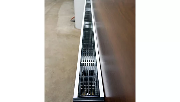
Another product just becoming available is the ECO-CON convector/radiator from Hydronic Heating Technologies in Cambridge, Ontario, Canada. Figure 4 shows the internal details of this product.
The internal fin-tube element has 5 1/2-in. tall aluminum fins attached to six copper tubes. The cast brass headers include top air vents and provide reverse return connections that help evenly distribute flow among the tubes. The front cover and top-side grill provide a neat and contemporary appearance, and only extend 3 3/4 in. out from the wall, as seen in Figure 5.
ECO-CON heat emitters are available in nominal 1-ft. length increments from 2 to 8 ft. Initial performance testing indicates an output of 502 Btu/hr., per foot of element length when the element is operating at an average water temperature of 120° and a flow rate of 4 gpm.
Tiny, but potent
As the water temperature within a heat emitter decreases, so does convective heat transfer. One way to compensate for this is to increase the air flow rate across the fin-tube element using blowers or fans. This has been done for decades in products such as wall convectors or kickspace heaters with internal blowers and similar products. The line voltage motors driving the blowers and fans in most of these products do not have stellar electrical-to-mechanical efficiency.
As the market for personal computers and other electronic appliances has grown over the last few decades, small fans using brushless DC motors were developed for cooling these devices. These fans can be operated at variable speeds and with very low electrical power requirements.
Worldwide, several companies have adapted this high-efficiency “microfan” technology to enhance the convective heat output from their heat emitters, especially under low water temperature conditions.
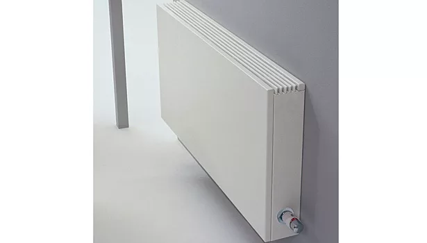
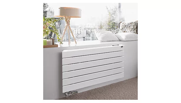
Figure 6 shows one example of a heat emitter from JAGA North America that can be equipped with a rack of microfans. JAGA refers to its fan-enhanced system as “DBE” (Dynamic Boost Effect).
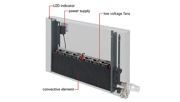
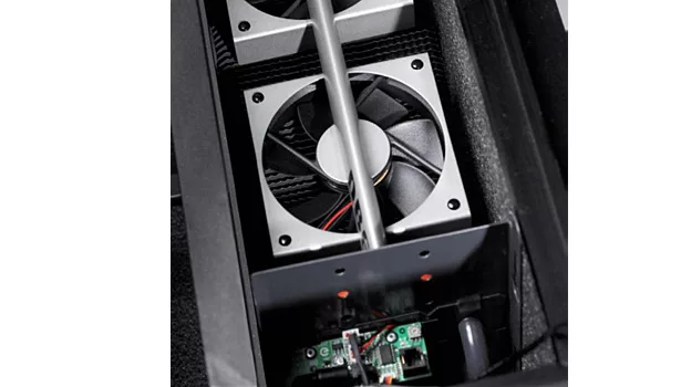
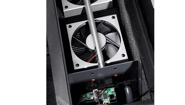
The internal construction of this heat emitter is shown in Figures 7a and 7b.
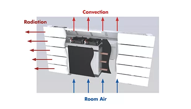
Notice the deep fin-tube element with multiple tube passes. This is where the microfans rest and their speed is controlled by a small electronic controller that measures incoming water temperature. At full speed each small fan only draws about 1.5 watts. The enhanced air flow created through the fin-tube element boosts heat output about 50% compared to the same element operating with only natural convection.
Water flow through the element can be controlled with a thermostat radiator valve as seen in Figures 6 and Figures 7a and 7b.
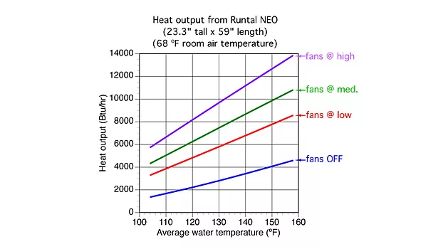
Runtal North America also is offering a combined radiator/convector with internal microfans. Its “NEO” unit is shown in Figures 8a and 8b.
During mild conditions, the NEO unit can be operated without any assistance from the internal microfans. During colder weather, the microfans can be switched on at any of three speed settings.
Figure 9 (on page 20) shows the rated output of an 8-tube-high (23.3-in.) by 59-in.-long Runtal NEO unit over a range of average water temperatures. These ratings assume the unit is operating in a room at 68° air temperature.
The JAGA (DBE) radiators as well as the Runtal NEO units require a source of 24 VAC to operate the microfans. This can be supplied by a small plug-in transformer located behind or below the unit. It also could be supplied by a central 120/24 VAC transformer in combination with low- voltage wiring routed to each of several panels. The latter usually is preferred when multiple microfan-equipped heat emitters are installed.
For the record, I have no professional involvement with any of the companies’ products that were shown and discussed. My intent is simply to show pme readers that such products are available in North America and are ready to facilitate broader use of low-water temperature hydronic systems.
Keep these products – and others that likely are to be forthcoming – in mind as you design systems around mod/con boilers, geothermal heat pumps, air-to-water heat pumps, solar thermal collectors, thermal storage systems or other sources of relatively low temperature water. Also, remember these products can be used in combination with radiant floor, wall and ceiling panels.
Think low temperature for high performance.
Looking for a reprint of this article?
From high-res PDFs to custom plaques, order your copy today!


