The Glitch & The Fix
Installation nightmare — how many problems can you spot?

Image courtesy of John Siegenthaler
The Glitch
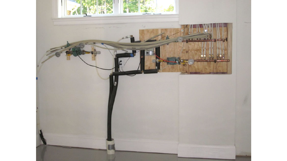
The photo in Figure 1 is the inside portion of a heating system supplied by a non-pressurized outdoor wood-fired furnace. The two PEX tubes coming up from the floor through the 4-inch PVC sleeve lead back to the outdoor furnace. On the right of those tubes is a floor heating subsystem powered by a cast iron circulator. Mixing is provided by a thermostatic 3-way valve. To the left of this mixing valve is a bypass between the supply and return tubes coming in from the outdoor furnace — which has its own circulator. To the left of the vertical tubes is an “expansion zone” going to another floor heating circuit seen on the far left of the photo. For what it’s worth, this collection of hardware is installed in a multi-million dollar home.
Do you see any issues with this installation?
FIGURE 1


Image courtesy of John Siegenthaler
The Fix
Aside from the fact that this system is unlikely to win awards for craftsmanship, there are several issues.
- Outdoor wood-fired furnaces are not boilers, they’re open-loop heat sources. Steel and cast iron components, such as the two circulators and two flow check valves seen in Figure 1 will corrode in open loop systems. Open loop applications require non-ferrous hardware.
- I can only surmise that this system was installed after the electrical inspector had left the premises. The line cords connecting the circulators and a junction box to the wall receptacle would not meet code.
- The thermostatic mixing valves shown are intended for use in domestic hot water systems. They likely have a Cv rating between 2.5 and 3.5. There are 7 floor heating circuits on the right side manifold. If we assumed a nominal 1 gpm flow rate per circuit, all that flow would have to pass through the mixing valve. A flow of 7 gpm through a device with a Cv of 3 would create a pressure drop of about 5.4 psi, which equates to a head loss of 12.6 feet. This head loss would be in addition to the head loss through the floor heating circuits. A 300-foot-long circuit of 1/2” PEX operating at 1 gpm will have a head loss of about 10.7 feet. This makes the total head loss of the mixing valve and floor circuits 23.3 feet, and that’s not counting losses through the flow check and other copper tubing.
Can the circulator provide a flow of 7 gpm at let's say 25 feet of head? Some “higher head” and higher power input models could, but most common zone circulators could not. This implies that the flow rate through the floor circuits is likely to be significantly less than the assumed 1 gpm. That will result in larger temperature drops and greater deviations in floor surface temperature. The bottom line: Don’t choke flow to radiant panel manifolds using low Cv mixing valves. - Take a look at how close the inlet of the circulator on the right side of the system is to the outlet of the thermostatic mixing valve. This will cause turbulent flow into the circulator, which increases operating noise. There should be a minimum of 10 diameters of straight pipe upstream of any circulator.
- If, (and it’s an if, since the outdoor furnace is not visible) portions of this piping are above the water level in the outdoor furnace, they will be under negative pressure relative to the atmosphere when the circulators are off. Any connection that’s not absolutely tight will allow air entry to the system.
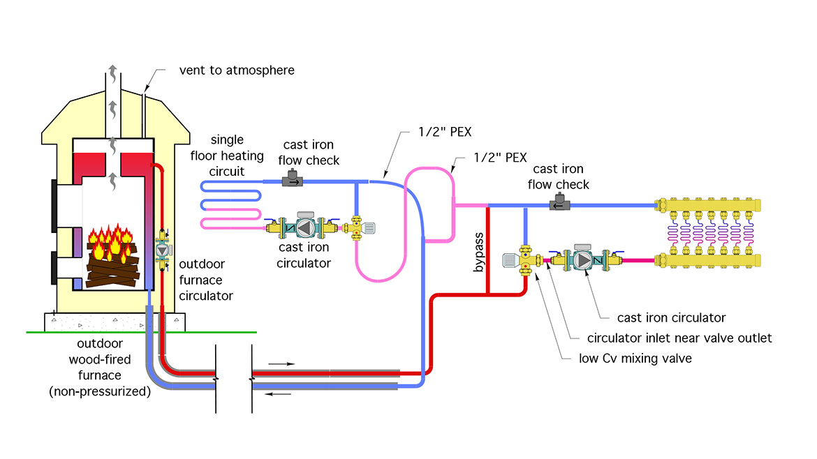
Figure 2 shows my best interpretation for how the components are connected based on the photo in Figure 1.
FIGURE 2


Image courtesy of John Siegenthaler
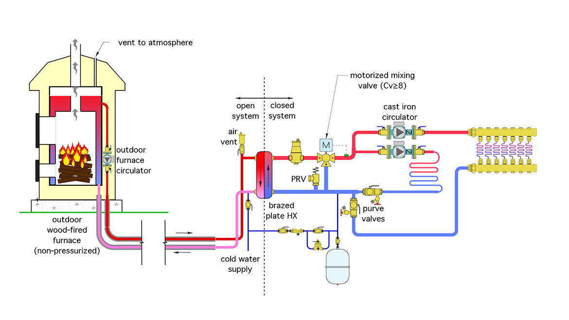
Figure 3 shows an alternative design that would serve the same floor heating circuits from the same outdoor wood-fired furnace, but eliminate some of the problems.
FIGURE 3


Image courtesy of John Siegenthaler
The outdoor furnace provides constant flow through the primary side of a stainless steel brazed-plated heat exchanger, which divides the overall system into open-loop and closed-loop subsystems. Everything on the right of the heat exchanger is now a closed loop. As such, it remains free of the constraints and nuances of open-loop systems (e.g., negative pressure issues, corrosion of ferrous metals, evaporation losses). Cast iron circulators are fine in what is now a closed-loop portion of the system.
Other necessary trim includes a central air separator, expansion tank, make-up water system, pressure relief valve and purge valve on each zone. Each zone circulator has an internal check valve. A motorized mixing valve with a minimum Cv of 8 provides accurate temperature control to both zones without the flow restrictions of a low Cv thermostatic mixing valve. A float-type air vent with an isolation valve is shown on the primary side of the heat exchanger.
Figure 3 also shows a valve to periodically add cold water to the open loop portion of the system, which is necessary due to evaporation losses from the outdoor furnace.
Looking for a reprint of this article?
From high-res PDFs to custom plaques, order your copy today!


