Renewable Heating Design | John Siegenthaler
An expensive lesson in hydronic fundamentals
What was, what is, and what could have been.

Image Source: travenian / iStock / Getty Images Plus
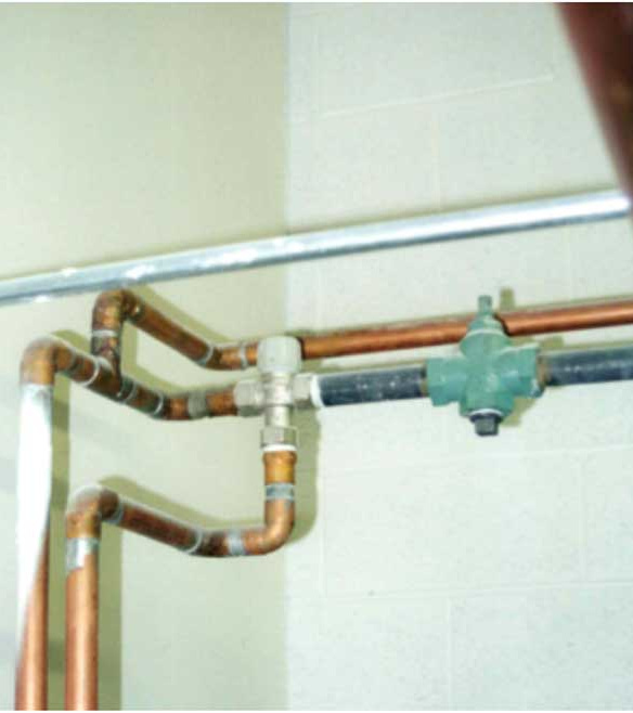
The schematic shown in Figure 1 is based on a real installation. You can see some of the installed components in Figures 2 and 3.
The system has an oil-fired cast iron boiler that supplies four floor heating manifold stations in a 7,000 square foot slab-on-grade building. The installer used 1-inch pipe size thermostatic mixing valves in each of the four zones — two of which had tile finish flooring, and two of which were covered with commercial carpeting glued to the slab.
The occupants complained that only certain areas of the floor, regardless of floor coverings, would feel warm. The building as a whole was not able to maintain thermostat setpoint. When I was asked to look at the system, I found the vent connector piping completely corroded (visible holes all the way through the underside of an elbow pipe), and rusty stains on the top of the boiler below the corroded elbow (visible in Figure 3). I also measured a very high temperature drop (at least 40° F) between the supply and return pipes leading to each active manifold station.
FIGURE 1


Figure 2

Figure 3
There are several things wrong with the original installation. Here’s a summary of the problems and their likely causes.
1. When water is pushed out the discharge port of a circulator, it only “cares about” getting back to the inlet port of that circulator. It will do so through whatever path(s) are available. In this system, the internal pathway from the hot port to the cold port of the mixing valve apparently had much lower hydraulic resistance compared to the intended flow path through the manifold stations. This resulted in most of the flow passing through the mixing valve rather than through the manifold stations, as depicted in Figure 4.
FIGURE 4


The abnormally high temperature drop measured across the manifold stations was the “clue” that pointed to an inadequate flow issue. It also explains why only a limited area of the floor felt warm. The beginning portion of each floor circuit was warm enough to transfer heat, but the “tail end” of each circuit was almost the same temperature as the room, and thus not able to transfer heat at a rate even close to what was required.
The fundamental principle: Whenever a mixing device is used to lower the water temperature from a heat source to the supply side of a low temperature heat emitter, the circulator must be installed between the mixing device and the heat emitter.
Beyond the misplaced zone circulators, several other errors are present in Figure 1. They include:
2. Most thermostatic mixing valves intended as safety devices in domestic hot water applications have relatively low Cv ratings. The Cv is the flow rate of water (in gpm) that will create a 1 psi pressure drop across the valve when it’s fully open. In this case, the listed Cv of the thermostatic mixing valves used was 3.9. This is quite restrictive in the flow path serving manifold stations with 6 to 8 circuits.
For a 300-foot-long 1/2-inch PEX circuit, a flow rate of 1 gpm is a reasonable guideline. To achieve a flow of 8 gpm through an eight circuit manifold station, the ∆P across the thermostatic mixing valve would have to be about 4.2 psi, which corresponds to a head loss of about 9.7 feet. That’s relatively high considering the head loss through a 300-foot-circuit of 1/2 inch PEX at 1 GPM is about 10.8 feet. A higher head circulator, placed correctly between the mixing valve and manifold station could probably make this work, but I suggest there are better options. Read on.
3. The position of the expansion tank connection relative to the circulators represents a “pumping toward” rather than “pumping away” configuration. As shown in Figure 1, the circulator is “pulling” flow rather than pushing flow through the circuit. Depending on system static pressure and temperature, it’s possible that sub-atmospheric pressure could be present at some locations in the circuit while the circulator is operating. This would allow air entry through anything less than a perfect seal at such locations.
The fundamental principle: Always pump away from the point where the expansion tank connects to the system.
4. The system in Figure 1 has no means of preventing sustained flue gas condensation in the boiler. This is why the flue connector, which was only about 6 months old when I first saw the system, was heavily corroded. Flue gases were condensing within the vent connector creating a puddle on the low side of an elbow, and eventually eating though it. The stains on the top of the boiler are the evidence.
The fundamental principle: All low-temperature heating systems supplied from conventional boilers must have a means of sensing and reacting to return water temperature.
Ideally, the boiler inlet temperature should be maintained above 130° F whenever possible.
Potential Revision No. 1
Figure 5 shows one revision of the system which assumes that two different supply water temperatures are required: One for the tiled floor areas and the other for the carpeted floor areas.
FIGURE 5


Two 4-way motorized mixing valves are used. The controls operating each of these valves can be set for the required supply water temperature setpoint, or better yet — an outdoor reset schedule. These controls also monitor the boiler inlet temperature, and when necessary, restrict or stop hot water from the boiler from entering the mixing valve. This provides consistent protection against sustained flue gas condensation.
If the 4-way mixing valves are located very close to the boiler, and the boiler has very low flow resistance (i.e., a cast-iron sectional boiler), and the header piping is generously sized, it’s not necessary to install a boiler circulator. The momentum of the water returning from the zones is sufficient to create adequate flow through the boiler. However, don’t do this with copper tube boilers or if the mixing valves can’t be located close to the cast iron boiler. In such cases, install a separate boiler circulator.
It is necessary to install two swing check valves (not spring-loaded check valves) to prevent flow reversal when some zones are on and others are off. All the zone circulators also have integral check valves to prevent flow reversal.
Potential Revision No. 2
The thermal resistance of low pile commercial carpet that’s glued to the floor slab may not be much higher than that of the floor tile. If this is the case, the system could be reconfigured to operate with a single supply water temperature, and single outdoor reset schedule. Only one mixing valve would be required, as shown in Figure 6.
FIGURE 6


The designer could investigate the option of using slightly closer tube spacing in the areas with carpet relative to the tube spacing in the tiled areas. The slightly closer spacing would compensate for slightly higher thermal resistance of the carpet relative to that of the tile. The goal is to get the supply water temperature of all circuits within about 5° F of each other under design load conditions. If this can be done, a single supply water temperature significantly reduces cost and complexity. The boiler is still protected by the controller operating the 4-way mixing valve.
What is
This system could also use a variable speed injection mixing assembly as an alternative to the 4-way mixing valve. In this case, a boiler circulator would definitely be required, as shown in Figure 7.
FIGURE 7


This was the way the system was reconfigured. The controller for the variable speed injection circulator operates based on outdoor reset control and is set to provide the higher supply water temperature required by the carpeted areas under design load conditions. This water temperature is slightly higher than needed for the tiled areas, but the zone thermostats prevent overheating. This reconfiguration solved the uneven floor heating issue and protects the boiler and the new flue piping from sustained flue gas condensation. A happy ending to a problem job.
What could have been
The above configurations assume that the zone circulators would remain in the system. However, if this system was being designed from scratch using hardware that’s available today, but not when the system was originally installed, I suggest the configuration shown in Figure 8 would be the simplest approach of all.
FIGURE 8


This system still assumes an oil-fired cast iron boiler, and thus the 4-way motorized mixing valve is still used to provide supply water temperature control (based on outdoor reset) and anti-condensation protection for the boiler.
This design also assumes that the tube spacing could be varied to allow a single supply water temperature (or single outdoor reset schedule).
Zoning is done using zone valves. A single variable-speed pressure-regulated circulator provides flow for the entire distribution system. It would be set for constant differential pressure and automatically change speed to maintain that differential pressure as zones open, and vice versa.
If the manifold stations differed substantially in the number of circuits they serve, it would be good to include balancing valves on each zone circuit. If the variation in number of circuits per manifold was small, the balancing valves on the individual manifold stations would likely suffice.
Owning It
The original installer recognized that mistakes were made and took full responsibility to reconfigure the system at his expense. No arguments, no litigation, just an honest contractor learning some lessons that hopefully he can apply across many future installations. Those lessons would have been less expensive if they were learned before the hardware was installed.
The take away: Study and understand hydronic fundamentals before attempting installations.
Looking for a reprint of this article?
From high-res PDFs to custom plaques, order your copy today!


