Hydronics Workshop | John Siegenthaler
Heat pumps open possibilities for DWH and hydronic-based cooling
Expanding a concept — part two.

An air-to-water heat pump installed by Mike Bellinger and David Dousharm of CNY Pipeworx, LLC. Photo courtesy of John Siegenthaler
Last month, we started out with a simple air-to-water heat pump system that provided space heating. We expanded that basic system to include an auxiliary heat source, such as a mod/con or electric boiler. We expanded it again to include chilled water cooling.
This month we’re adding two more functions to the system. Let’s start with domestic water heating. The system in Figure 1 is very similar to the system in Figure 3 of last month’s column.
FIGURE 1
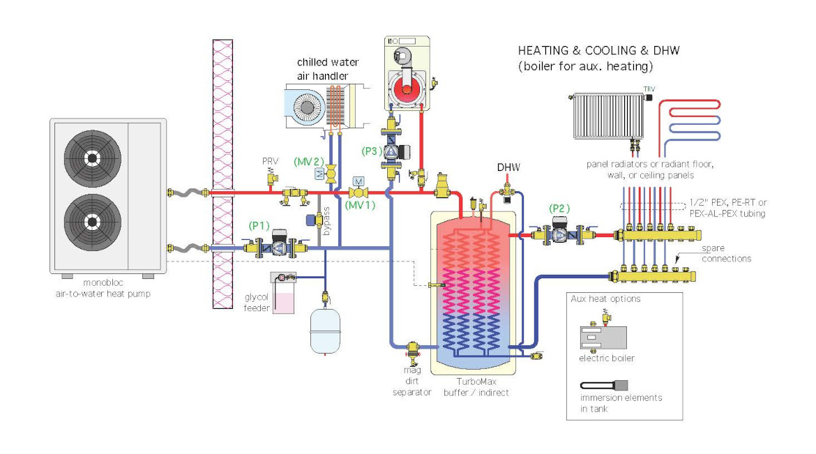 Courtesy of John Siegenthaler
The difference is mostly in the tank. In this case, it’s a reverse indirect water heater with extra ports allowing it to also function as a buffer tank for a highly zoned distribution system.
One tank that offers these features is the TurboMax from Thermo 2000.
The air-to-water heat pump, or the mod/con boiler, maintains the temperature in the shell of this tank between 115° F and 125° F, 24/7, year-round. This allows the internal coils to fully heat domestic water to 110° F on single pass through the internal coils. A thermostatic mixing valve ensures that the domestic hot water supplied to the building’s plumbing distribution system never exceeds 120° F.
The two side ports on the right side of the tank supply the same homerun distribution system described in last month’s column. The heat emitters could be panel radiators equipped with thermostatic radiator valves, or radiant panel circuits. They could even be a “mix” of heat emitters provided that they are all sized to operate in the supply temperature range of 115° to 125° F under design loads.
Divide the zones up as you like. Each room with a panel radiator and thermostatic valve becomes its own zone. Likewise, if you want to zone using thermostats, just add 24 VAC valve actuators to each manifold circuit valve.
We Got This
Consider a situation where there is a simultaneous call to heat the reverse indirect/buffer tank and cool the building. Both can occur during warm weather since the tank temperature needs to be maintained to provide DHW.
In this case, the system controls must prioritize one of these loads over the other. The most common prioritization is that of domestic water heating over cooling. The reason is that the heat pump, or the boiler, can quickly recover the temperature in the tank in just a few minutes. During this time, the blower in the air handler could continue to operate but there would be no chilled water flow through the coil. Once the tank temperature has reached the upper limit setting the system transitions back to cooling.
But wait! When this changeover occurs, the piping between the heat pump and reverse indirect tank are still filled with hot antifreeze solution. If motorized ball valve (MV2) immediately opens, a “slug” of hot fluid will pass through the coil in the air handler. The resulting burst of heated air from the registers is guaranteed to be noticed since the system is supposed to be cooling the building.
This undesirable effect is avoided by temporarily opening the bypass valve to allow flow through the heat pump while keeping motorized ball valve (MV2) closed until the fluid temperature leaving the heat pump drops to 55° F or lower. In most systems, that’s only going to take two or three minutes. At that point, motorized ball valve (MV2) opens, the bypass valve closes, and nice cool/dehumidified air starts passing out of the registers.
A somewhat similar situation occurs when the system is operating in cooling and gets the priority call to heat the reverse indirect tank. Although less likely to be noticed, if motorized ball valve (MV1) immediately opens, a “slug” of chilled fluid in the piping leading to the heat pump passes into the reverse indirect tank. This undesirable effect is again avoided by opening the bypass valve while keeping (MV1) closed until the fluid leaving the heat pump reaches the temperature in the upper portion of the tank. At that point, (MV1) opens, the bypass valve closes, and hot fluid passes into the shell of the reverse indirect tank.
These “temperature decisions” can be made using setpoint and differential temperature controllers. Looking forward, an integrated controller that could handle these and other logic requirements of the system will hopefully be developed.
Keeping it Fresh
Many new homes are built to low air leakage requirements. Heat recovery ventilators are often specified to keep interior air fresh without wasting all the thermal energy in the exhaust air stream.
The system in Figure 1 already uses a supply air ducting system. That same ducting can deliver fresh air from the heat recovery ventilator (HRV) as shown in Figure 2.
FIGURE 2
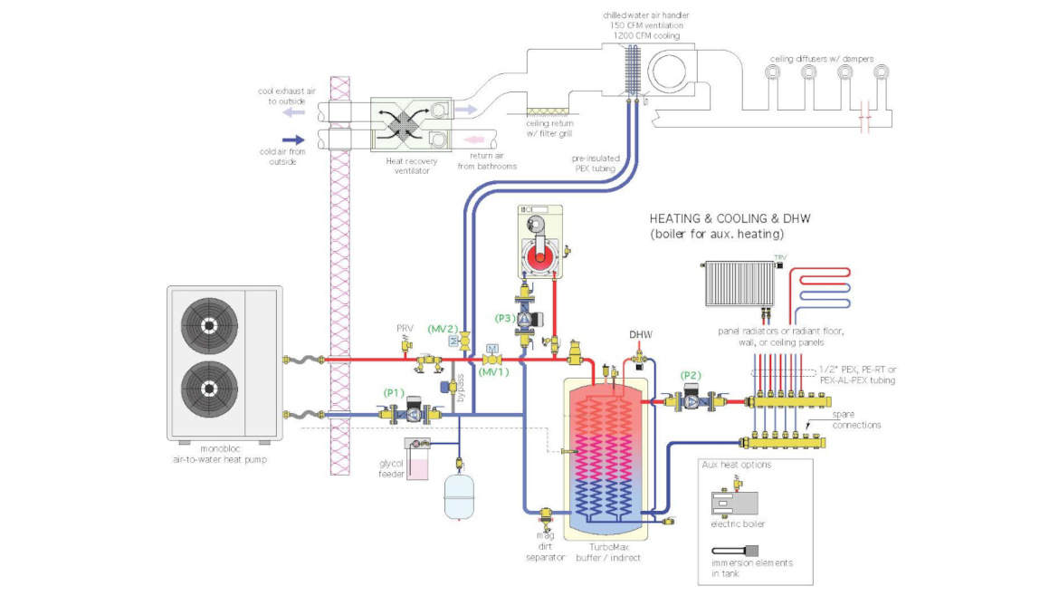 Courtesy of John Siegenthaler
During the heating season, the HRV delivers fresh air to the return side of the air handler. The ECM blower in the air handler operates at a low 150 cfm air flow rate 24/7. That air flow rate is adequate to move the fresh air through the supply ducting with minimal power input to the blower. Stale air is collected from the bathrooms. It passes through the HRV where about 65-70% of the heat it contains is transferred to the incoming cool/fresh air.
During cooling operation, the air flow rate of the ECM blower is increased to 350-400 cfm per ton of cooling capacity. The HRV continues to operate at its relatively low air flow rate, injecting fresh air on the return side of the air handler, and exhausting stale air outside.
In typical residential applications where cooling loads are often 2-4 tons (24,000 to 48,000 Btu/h) the air handler can be supplied through either 3/4” or 1” pre-insulated PEX tubing. This tubing is easily routed through framing cavities and provides a continuous insulation and vapor seal all the way from the mechanical room to the air handler.
Be sure that all tubing and piping components that come into contact with chilled fluid are insulated and vapor-sealed to prevent condensation and subsequent dripping. Don’t cheat on the insulation quality or its installation. Any gaps where surrounding air can contact chilled water piping or components will result in condensate accumulation, and that will quickly lead to dripping, staining and eventually mold. Glue all joints in the insulation, and use adhesive-backed insulation tape when necessary to fit oddly shaped components. If available, install molded insulation shells on circulators and seal up all the seams.
From One to Four
For decades hydronics has been known as a method for heating buildings. When properly executed it has earned a reputation for unmatched comfort, energy efficiency and reliability. Hydronic-based cooling for residential and light commercial buildings was extremely rare.
The availability of heat pumps, and air-to-water heat pump in particular, open the possibility of retaining all these desirable heating season qualities while adding whole-house cooling, and ventilation that matches the needs of modern buildings. Modern hydronics technology provides the “glue” to put it all together.
Looking for a reprint of this article?
From high-res PDFs to custom plaques, order your copy today!


