The Glitch & The Fix: April 2025
Unexpected results: heat pump system at low outdoor temperatures
Consider the “dual temperature” heat pump system shown in figure 1
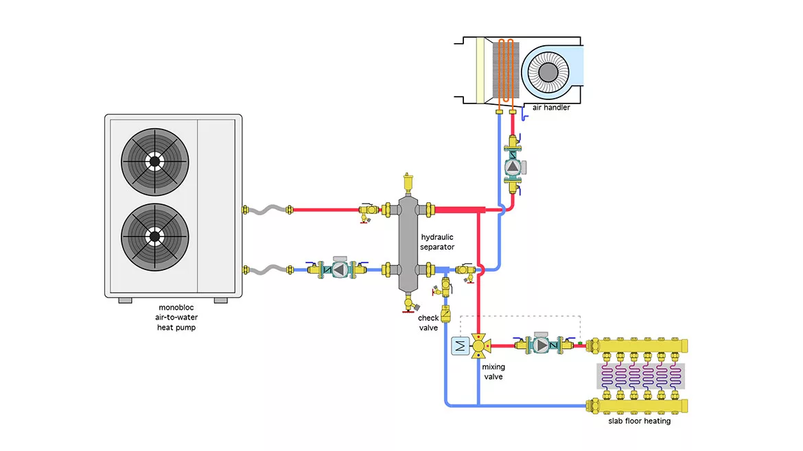
Image courtesy of John Siegenthaler
The air-to-water heat pump has a nominal 4-ton (48,000 Btu/hr) heat output rating. It supplies an air handler as well as a heated concrete slab. At design load conditions the air handler is rated for 20,000 Btu/hr with a supply water temperature of 120 ºF. The slab is designed to release 20,000 Btu/hr when supplied with water at 105 ºF.
To accommodate these conditions the installer decides to set up the heat pump controls for a supply temperature of 120 ºF, and use a motorized mixing valve to reduce the water temperature to the floor heating circuits.
When only the air handler is operating the heat pump is able to supply the 120 ºF water. Whenever the heated slab is operating by itself the heat pump has no problem providing the required water temperature. However, when the floor heating zone and the air handler are operating at the same time and the outdoor air temperature is below 24 ºF the fluid temperature leaving the heat pump can’t climb above 103 ºF. Why is this happening, and what can be done to either prevent it on a new install, or correct it on an existing system? What other hardware details are missing in figure 1?
What’s Wrong
All hydronic systems seek to operate at “thermal equilibrium.” That’s a steady state condition where the rate of heat production by the heat source is the same as the rate of heat dissipation by the load.
The greater the heat emitter surface area available to dissipate heat, the lower the water temperature will be when thermal equilibrium is achieved.
Figure 2 shows how the heat output of the floor slab and air handler vary based on supply water temperature. The room air temperature is assumed to be 70 ºF.
FIGURE 2

Image courtesy of John Siegenthaler
The orange line is the output of the air handler, reaching 20,000 Btu at a supply water temperature of 120 ºF. The pink line is the output of the slab, reaching 20,000 Btu/hr at a supply water temperature of 105 ºF. The red line is the combined output of the air handler and slab when they operate together.
The green curve is the heat output of the heat pump. Even though the heat pump has a “nominal” heat output of 48,000 Btu/hr, its actual heat output is a strong function of outdoor air temperature as well as leaving water temperature.
The point where this green curve crosses the red line is the thermal balance point for this system. It’s where the output of the heat pump matches the combined heat dissipation rate of the distribution system. In this system that point corresponds to a supply water temperature of 103 ºF, and happens to occur when the outdoor temperature is about 24 ºF. At outdoor temperatures above 24 ºF the heat pump has ample capacity. But at outdoor temperatures below 24 ºF it doesn’t have sufficient capacity to meet both loads.
The Fix
One way to get the water temperature to go higher when both the air handler and slab are operating is to use a heat pump with significantly more heat output relative to the design load of the building. This would shift the balance point to the right, but it would certainly add cost, and might cause short cycling under partial load conditions, especially when only the air handler is operating.
A more plausible option is to add supplemental heating to the system. That supplemental heating capacity might come from of electric heating elements within the heat pump. It could also come from a boiler. Figure 3 shows the latter.
FIGURE 3
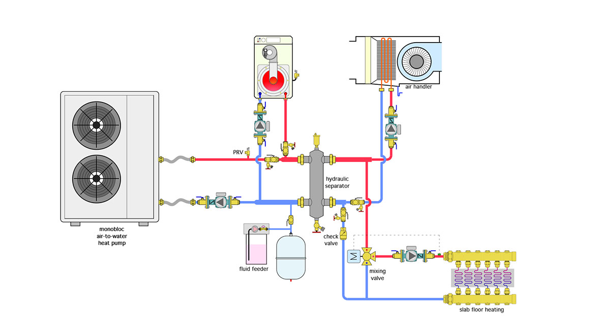
Image courtesy of John Siegenthaler
The supplemental boiler is piped in parallel with the heat pump. Each has its own circulator with check valve. Each heat source can operate as the system’s sole heat source or they can operate together during periods of high demand, such as recovering the floor slab from a temperature setback. The boiler might be turned on by a supplemental heat contact in the heat pump, or it might be turned on by a 2-stage outdoor reset controller that treats the heat pump as stage 1 and the boiler as stage 2. The objective would be to operate both heat sources to maintain a supply water temperature of 120 ºF on the load side of the hydraulic separator, at design load conditions. The motorized mixing valve would reduce the supply temperature to the floor heating circuits to 105 ºF at design load.
Other details included in figure 3 compared to figure 1 include a fluid feeder, an expansion tank, and a pressure relief valve on the heat pump piping that would protect it against overpressure should it be isolated from the remainder of the system.
Looking for a reprint of this article?
From high-res PDFs to custom plaques, order your copy today!


