Combining outdoor reset control and heat pumps
Don’t overcook it.

Figure 1.

Figure 2.

Figure3.

Figure 4.


In past columns, we’ve discussed geothermal water-to-water heat pumps and air-to-water heat pumps via hydronic heat sources. Both can be a great match to low-temperature hydronic distribution systems.
The word “geothermal” is currently one of the hottest buzzwords in the HVAC industry. It’s very evident that geothermal heat pump systems are quickly gaining market share in a wide range of buildings. Even the feds think it’s worth pitching in 30 cents on the dollar to help put one of these systems in your house.
Although not currently as well-known as geothermal, air-to-water heat pumps are gaining traction in North America. At least six manufacturers now offer AWHPs that are appropriate for residential and light commercial hydronic systems.
I think the hydronics industry has a great opportunity to capitalize on the growing interest in heat pumps. We need to promote how both geothermal and AWHPs can be combined with low-temperature hydronic distribution systems to deliver the combination of low operating cost and superior comfort. Beyond this combination is the opportunity to use either type of heat pump as the primary means of heating domestic water and providing chilled water for cooling.
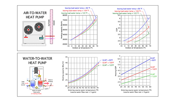
Both geothermal water-to-water heat pumps and AWHPs thrive on low-load water temperatures. Although either type of heat pump can safely operate with leaving load water temperatures as high as 120° F, anything that can be done to lower the load water temperature will improve both heating capacity and coefficient of performance.
This month I want to discuss ways to maximize both the heating capacity and COP of heat pumps using a technique that’s already familiar to most seasoned hydronic professionals — outdoor reset control.
The lower the better
The heating performance of geothermal water-to-water and air-to-water heat pumps is very sensitive to the water temperature leaving their condensers. The lower this leaving load water temperature, relative to the temperature of the source water, the higher the heating capacity and COP. The graphs in Figure 1 bear this out for both types of heat pumps.
As designers, there isn’t much we can do about the temperature of the source water entering a geothermal heat pump, short of designing a very oversized earth loop, which will only yield an incrementally higher entering source water temperature. In the case of air-to-water heat pumps, we’re at the mercy of the outdoor air temperature.
However, we can do several things to lower the load water temperature.
First, design a hydronic distribution system that can deliver design load heat output while operating at the lowest practical supply water temperature. Radiant floor, wall and ceiling panels are likely the best opportunity. These would be followed by generously sized panel radiators, especially those with internal microfans to boost convective heat output at lower water temperatures. Next would come generous lengths of low-temperature, fin-tube baseboard.
The criteria I suggest is to provide a distribution system that can supply design load using supply water temperatures no higher than 120°. Feel free to design around even lower supply water temperatures if it’s practical and cost-effective.
Next, use an outdoor reset controller to operate the heat pump at the lowest possible water temperature that can still supply the heating load.
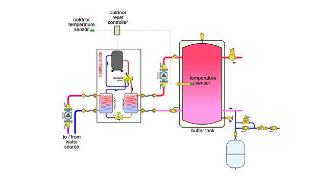
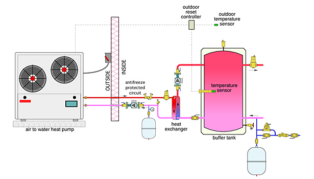
One of the easiest ways to do this is to pipe the heat pump into a buffer tank and insert the supply water temperature sensors into a properly located well in that tank, as shown in Figure 2 for a geothermal heat pump and Figure 3 for an air-to-water heat pump.
The air-to-water heat pump is connected to the balance of the system using an antifreeze-protected circuit and a generously sized brazed-plate heat exchanger. This eliminates concerns of freezing, even during a prolonged power failure. The heat exchanger should be selected based on an approach temperature difference no higher than 5° when transferring the maximum heating capacity of the heat pump. This is the temperature difference between the heated antifreeze supplied into the “hot” side of the heat exchanger and the water temperature leaving the “cooler” side of the heat exchanger.
Target water temperature
Both schematics show an outdoor reset controller. Whenever it is powered on, this controller measures the current outdoor temperature and uses it, along with its settings, to calculate the ideal target water temperature required by the distribution system. It then compares this calculated target temperature to the temperature measured by the sensor in the buffer tank.
If the measured temperature is more than one half the differential below the target temperature, a pair of contacts inside the reset controller close. This contact closure turns on the heat pump. The heat pump then turns on the circulator(s) between itself and the buffer tank. If it’s a geothermal water-to-water heat pump, the earth loop circulators also are turned on.
The heat pump continues to add heat to the buffer tank until one of two things happens: the heating demand is satisfied at the room thermostat, which turns off the outdoor reset controller and the heat pump; or the temperature inside the buffer tank reaches one half the differential above the target temperature calculated by the outdoor reset controller.
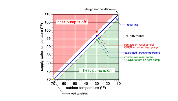
Figure 4shows a typical reset line for an outdoor reset controller operating a heat pump in such a system.
The target temperature is represented by the blue “reset” line. The white gap surrounding this line represents the differential setting of the reset controller. In this case the differential is 5° and centered on the reset line. The differential is necessary to prevent the reset controller from short-cycling the heat pump.
Consider the situation when the outdoor temperature is 30°. The calculated target temperature, under this condition, is 97°. The lower dashed line represents a temperature that is always 2.5° F (e.g., half the differential) below the target temperatures. When the outdoor temperature is 30°, the lower dashed line indicates a temperature of 97° - 2.5° = 94.5°. If the measured temperature in the buffer tank is at or below this temperature, the outdoor reset controller turns on the heat pump.
The upper dashed line represents a temperature that is always 2.5° above the target temperature. When the outdoor temperature is 30°, the upper dashed line indicates a temperature of 97° + 2.5° = 99.5°. If the measured temperature in the buffer tank is at or above this temperature, the heat pump is off.
The differential can be adjusted on most outdoor reset controllers. Wider differentials yield longer operating cycles for the heat pump, which leads to less stress on components. However, wider differentials also allow greater departure between the target water temperature and the water temperature in the buffer tank.
This means a wider variation in supply water temperature to the distribution system. Given that many low-temperature distribution systems are sensitive to minor water temperature variations, I suggest differentials no wider than 10°.
Recent testing of air-to-water heat pumps operated by outdoor reset control show increases in seasonal efficiency of 10% to 18%, based on different climate locations. The electrical energy savings associated with such a boost in seasonal efficiency would likely pay for the outdoor reset controller in under one year. It’s a no-brainer.
It also shows how technology that’s already familiar to most hydronic professionals — but not necessarily by those outside the industry — can “amplify” the benefits of renewable energy heat sources. Use it where you can.
Looking for a reprint of this article?
From high-res PDFs to custom plaques, order your copy today!


