Controlling wood-fueled biomass boiler systems: Part 2
Cooperative effort.

Figure 1.

Figure 2.

Figure 3.
Every elegant hydronic piping assembly deserves an equally elegant control system.
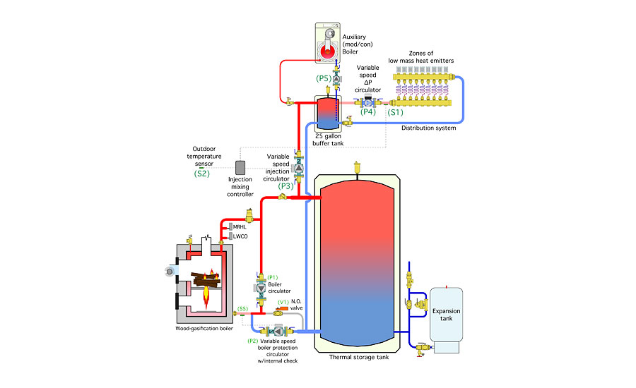
That was the closing thought in last month’s column where we examined an “elegant” piping approach for a system with a wood-gasification boiler as its primary heat source, and a mod/con boiler as its backup. It’s shown again in Figure 1 (see above).
This system has a thermal storage tank that soaks up surplus heat output from the wood-gasification boiler. It also has a 25-gal. buffer tank to protect the mod/con boiler against short-cycling as it faces off against a highly zoned distribution system.
Variable-speed circulators are used for protecting the wood-fired boiler against sustained flue gas condensation and controlling heat injection to the distribution system. This piping layout even allows for thermosiphon flow between the thermal storage and the wood-gasfiication boiler to protect the latter from overheating during a power outage.
In this month’s column, I’ll show how this overall system can be controlled.
A wide spectrum
Several possible ways are available to control a system like this. They range from a hard-wired grouping of individual controllers, each specific to one of the required control tasks, to a customized programmable logic controller, to one or more analog-to-digital converters that shuttle information between various sensors or controlled devices and a web-enabled PC that makes all the control decisions.
When making hardware selections for a system, it’s important to ask yourself this question: Would a reasonably competent HVAC technician be able to maintain the system I’m designing, replacing components if necessary, to keep the system operating for at least the next 20 years?
Although it’s hard to speculate on exactly what devices will be available that far into the future, I feel there’s a better chance of obtaining suitable replacements for basic control devices such as relays and relatively simple temperature controllers, in comparison to replacing highly customized multifunction controllers and the software or firmware they rely on.
Although the control system I’m going to show you uses specific makes and models for two controllers, other products could be substituted, if necessary, with relatively minor (if any) required wiring changes.
Figure 2(see above) shows the piping system from Figure 1 along with some added controls and sensors. I’ve also added a subassembly to the right side of the thermal storage tank to provide on-demand domestic water heating, and thus turn the previous heating-only system into a combisystem. You can read more about the details of this domestic water heating strategy in the June 2012 Hydronics Workshop column titled “Sidearm revamp”.
Figure 3(see above) shows a ladder diagram for the control wiring used on this system.
Notice all the components that are controlled, or part of a control function, are given designations such as (P1), (S1), (TEK156) or (R2-1). Many of these designations appear in both the piping and electrical drawings. As such they can be cross-referenced when studying how the system operates.
Documenting the design
Put yourself in the shoes of a reasonably competent technician who has never seen this combisystem before. That tech happens to be on call when the system does something abnormal. His job is to diagnose what’s wrong and fix it.
This process starts by trying to understand how the system should operate when everything is working correctly. Without good documentation, this is going to be a slow, tedious and frustrating process. Some techs, if given the opportunity, would just throw up their hands and walk out, mumbling about how the original installer was an idiot to ever put together such a system. That’s a shame if the problem is as simple as a temperature sensor that might have detached from a pipe because of a broken zip tie.
With good documentation, the tech would be able to quickly familiarize himself with how the system operates. B follows A, C follows B and so forth. From there he should be able to systematically trace down where the fault lies, identify the hardware that’s at the root of the problem, and repair or replace it as necessary.
The best way to describe how a system works is to write a complete description of operation for it. This is simply a written description of control sequences in the same order they occur, along with identifying the specific devices involved in each sequence.
Break the overall control system into operating modes and narrate the sequence of operation in each mode. Start with what initiates a specific mode and use generous references to the component designations. End the mode narration with what completes the process.
Here is a complete description of operation for the combisystem represented by Figures 2 and 3:
1. Wood-gasification boiler operation.
A fire is kindled in the boiler and after building for a few minutes, the primary combustion chamber is loaded full of wood and the boiler’s switch is turned on. This turns on the boiler’s combustion blower and circulator (P1), and initiates gasification mode operation. It also supplies line voltage to circulator (P2). The electronics within circulator (P2) monitor the temperature of the boiler inlet at sensor (S6).
When the temperature at sensor (S6) rises to 130° F, circulator (P2) increases speed. If the temperature at sensor (S6) drops below 130°, the speed of circulator (P2) is reduced to a minimum. The speed of circulator (P2) will continually adjust during the burn cycle in an attempt to keep the boiler inlet temperature at a minimum of 130°. This prevents the wood-gasification boiler from operating with sustained flue gas condensation.
Flow created by circulator (P2) passes through the boiler and on to the upper header of the thermal storage tank. If the space-heating load is not active, this flow passes into the thermal storage tank. If the space-heating load isactive, some or all the flow can be drawn through injection circulator (P3).
2. Overheat protection.
The normally open motorized valve (V1) opens whenever utility power is lost. This allows an uninhibited flow path between the wood-gasification boiler and thermal storage tank through which thermosiphon flow can develop to move residual heat from the boiler to the storage tank.
A spring-loaded, normally closed, test switch (TSW1) is wired in series with the motorized valve (V1). This switch can be pressed to open its contacts and break line voltage to (V1) to verify it opens correctly. This test should be performed twice each heating season. Switch (TSW1) closes its contacts when its button is released.
3. Heat transfer to distribution system.
Upon a demand for space heating from any of the thermostats (T1-T6), 24VAC is passed to the associated valve actuator (VA1-VA6). When the valve actuator reaches its fully open position and internal end switch closes, the end switch passes 24VAC to relay (R1). A normally open contact (R1-1) closes to turn on the distribution circulator (P4), which is set to operate in a constant differential pressure control mode. 24VAC also is sent to the differential temperature controller (TEK156) and injection mixing controller (TEK356).
The (TEK156) controller measures the temperature difference between the water returning from the distribution system at sensor (S4) and the tank header at sensor (S3). When the temperature at (S3) is at least 5° higher than at (S4), a contact in (TEK156) closes to pass line voltage to the injection mixing controller (TEK356).
The injection mixing controller (TEK356) measures the outdoor temperature at sensor (S2) and uses this value, along with its settings, to calculate the target supply water temperature to the distribution system. It compares this target temperature to the temperature measured at sensor (S1).
If the temperature at (S1) is lower than the target supply temperature, the (TEK356) controller increases the speed of injection circulator (P3) to inject heated water into the distribution system in an attempt to bring the temperature at (S1) up to the target temperature. If the temperature at (S1) is higher than the target supply temperature, the (TEK356) controller reduces the speed of injection circulator (P3) to bring the temperature at (S1) down to the target temperature.
This process continues unless or until the temperature at (S3) become less than 3° higher than at (S4). This is typically the result of the fire dwindling in the boiler or the depletion of useful heat in the storage tanks. When this condition is detected, the contact in (TEK156) opens to break line voltage to the (TEK356) controller, and thus turn off injection circulator (P3). This prevents heat generated by the auxiliary boiler from being inadvertently conveyed into the thermal energy storage tank.
4. Auxiliary boiler operation.
The auxiliary boiler is enabled to operate by a relay contact in the (TEK356) controller. Closure of this contact passes 24VAC to the coil of time delay relay (TDR1), which then begins its timing for up to 15 minutes. This adjustable time delay allows sufficient time to warm the 25-gal. buffer tank and establish quasi-steady operation of the distribution system before commiting to operation of the auxiliary boiler.
When the time delay of relay (TDR1) has elapsed, it closes its normally open contact (TDR1-1), which completes a 24VAC circuit that allows the auxiliary boiler to fire. When turned on, the auxiliary boiler measures the supply water temperature at sensor (S7) and the outdoor temperature at sensor (S8). It operates based on its internal reset controller to keep this temperature close to the calculated target supply temperature.
5. Domestic water heating mode.
Whenever there is a demand for domestic hot water of 0.6 gpm or higher, a flow switch within the electric tankless water heater (ETWH) closes. This closure supplies 240 VAC to the coil of relay (R2). The normally open contacts (R2-1) close to turn on circulator (P6), which circulates heated water from the upper portion of the thermal storage tank through the primary side of the domestic water heat exchanger (HX1).
If the domestic water leaving (HX1) is fully heated, it flows through the tankless heater but the heating elements remain off. The water flows on to an ASSE 1017-rated mixing valve, which ensures a safe delivery temperature to the fixtures. Whenever the demand for domestic hot water drops below 0.4 gpm, circulator (P6) and the tankless electric water heater are turned off.
If you want to study this system more, print out the piping diagram (Figure 2) as well as the electrical diagram (Figure 3) and put them side by side. Then, as you read each sentence in the description of operation, find the referenced components in both figures. Take your time and be sure you understand the control handoffs from one control device to the next.
This system shows how modern hydronics technology can accommodate the unique operating requirements of a wood-gasification boiler, enabling it to cooperate with the remainder of the system to deliver uncompromised comfort using a renewable energy source.
Don't forget about maintenance. If you’re working with a wood-gasification boiler or a pellet-fired boiler, it’s important to ensure all aspects of the boiler operation are inspected and maintained on a regular basis, and at least once each year. Always inspect the chimney and vent connector piping for any signs of creosote and clean them if there is any accumulation. Replace any sections of vent piping that show signs of corrosion.
Always test the boiler inlet protection controls and the ability of the boiler, while operating with a full fire, to dissipate heat in a power-out situation. Test the boiler’s safety controllers such as a low-water cutoff and manual reset high limit. Test the normally open zone valve to ensure it opens on a power failure. Finally, test that the boiler’s pressure relief valve works properly. If it dribbles after testing, replace it.
Read here for Piping for wood-fueled biomass boiler systems: Part 1.
Looking for a reprint of this article?
From high-res PDFs to custom plaques, order your copy today!