Using wood-gasification boiler for space heating and repurposed thermal storage tank
January 2014 The Glitch and The Fix

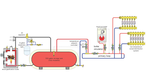
January 2014 Glitch drawing: A homeowner wants to use a wood-gasification boiler as his primary source of space heating and a propane-fueled boiler to automatically come on for backup. The owner has read that a generously sized thermal storage tank is necessary to allow a gasification boiler to operate at consistent high efficiency. He finds a local source for a 500-gal. propane storage tank and has it “repurposed” with new piping connections. The installation is shown above.

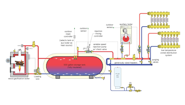
January 2014 Fix drawing: All pressurized wood-fired boilers need a heat dump provision to which heat can be sent if a power failure occurs when the boiler is firing. These boilers also require protection against sustained flue gas condensation when the storage tank is at a low temperature.
The loading unit shown in the Fix drawings handles both details. During a power failure, it allows thermosiphon flow between the boiler and storage tank. It also contains a thermostatic mixing assembly that boosts the boiler inlet temperature.>


The Glitch
A homeowner wants to use a wood-gasification boiler as his primary source of space heating. He also wants a propane-fueled boiler to automatically come on for backup should he decide not to tend the fire, or if he is away. The owner has read that a generously sized thermal storage tank is necessary to allow a gasification boiler to operate at consistent high efficiency.
He finds a local source for a 500-gal. propane storage tank and has it “repurposed” with new piping connections. He hires an installer to put these components together, along with the balance of system. The installation is shown below.
A setpoint controller monitors the temperature at the top of the storage tank. It turns on circulator (P1) whenever there is a call for heat and the tank’s temperature is above 110° F.
The mod/con boiler has a system supply sensor that continually measures the water temperature supplied to the manifold stations. If this temperature drops below the minimum acceptable water temperature determined by the boiler’s reset controller, the boiler and boiler circulator are turned on to provide backup heat.
Several things are incorrectly installed or missing in this situation. Can you find at least six things that should be changed?
The Fix
Here a list of some things that need modifying. Refer to the Fix drawing to see the changes implemented.
1. All pressurized wood-fired boilers need a heat dump provision to which heat can be sent if a power failure occurs when the boiler is firing. These boilers also require protection against sustained flue gas condensation when the storage tank is at a low temperature.
The loading unit shown in the Fix drawings handles both details. During a power failure, it allows thermosiphon flow between the boiler and storage tank. It also contains a thermostatic mixing assembly that boosts the boiler inlet temperature.
2. The 9-gal. expansion tank shown in the Glitch drawing, while likely “generous” for a typical residential hydronic system, is much too small to handle the expansion of 500 gal. of water, plus the water in the remainder of the system. The 44-gal. tank shown is representative of the size necessary for the system assumed in this schematic. The expansion tank size for a given system should always be verified through proper sizing methods.
3. The piping entering the top of the storage tank in the Glitch drawing will create vertical jets that break up stratification within the tank. This is undesirable. The piping connections in the Fix drawing have been repositioned to enhance stratification within the tank.
These connections also allow the warmest water entering the tank from the boiler to “slide” along the top of the tank toward the hot water outlet connection. This allows relatively hot water to be drawn from the tank without having to warm all 500 gal. of water.
4. The original installation does not have a means of regulating the water temperature supplied from the storage tank to the low-temperature distribution system. It’s very possible the storage tank could reach some very high temperatures (180° to 200° F). Such temperatures are much too high to send directly to the low-temperature distribution system.
The correction is to convert circulator (P1) into a variable-speed injection pump. The controller driving this circulator monitors the temperature supplied to the zones and regulates the injection pump speed to maintain an adequate supply temperature based on outdoor reset control.
5. The distribution system shown in the Glitch drawing is not a primary/secondary system. The zone circuits are connected across the upper and lower horizontal piping, treating the pipe as headers rather than as a primary loop.
In the Fix drawing, the right ends of the pipe have been capped. The “primary circulator” has been eliminated and the piping is labelled as “generously sized headers.” Such sizing allows the zone circulators to provide flow through the two sets of closely spaced tees that connect to each heat source.
6. Allowing the mod/con boiler to come on whenever the tank temperature drops below a specified temperature will ultimately use the mod/con boiler to keep the storage tank warm. This is very undesirable. Instead, circulator (P1) should be disabled whenever the mod/con boiler is operating. The latter detail prevents water heated by the mod/con boiler from circulating into the storage tank.
The necessary logic is provided by the reset controller shown in the Fix drawing. Upon a demand for heating, it measures storage tank temperature and determines whether the storage tank or auxiliary boiler serves as the heat source. It then energizes the selected heat source.
7. Purging valves have been added at key locations.
8. A second air separator has been added to the distribution side of the system.
9. The boiler piping in the Glitch drawing is incorrectly reversed at the closely spaced tees.
10. Before committing to the use of a repurposed propane tank, be sure of the following:
• That any welding done meets applicable code (such as ASME Section VIII);
• If the tank has stored propane, be sure to have it internally washed to remove any residual of mercaptan (the odorant used to give propane its putrid smell); and
• That the tank is fully pressure-tested after welding.
Looking for a reprint of this article?
From high-res PDFs to custom plaques, order your copy today!


