Multiple heating zones for hydronic and radiant applications
March 2014 The Glitch & The Fix

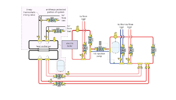
March 2014 Glitch drawing: The system above was intended to supply one high-temperature heating zone, a couple of medium-temperature zones and two zones of floor heating for a garage and breezeway where antifreeze protection was needed. The medium-temperature water was created by a variable-speed injection pump. The temperature to the antifreeze-protected zones was regulated by two thermostatic mixing valves.

March 2014 Fix drawing: Given all the circulators, you might think there would be no issues getting flow into all the nooks and crannies of the above system. However, every set of closely spaced tees is a point of hydraulic separation. Flow in the circuit coming into the side ports of a pair of tees induces very little flow in the circuit passing through the end ports of these tees.


The Glitch
The piping schematic shown above is a partial representation of a real installation. I received an SOS call on this one last winter. The system was intended to supply one high-temperature heating zone, a couple of medium-temperature zones and two zones of floor heating for a garage and breezeway where antifreeze protection was needed.
The medium-temperature water was created by a variable-speed injection pump. The temperature to the antifreeze-protected zones was regulated by two thermostatic mixing valves.
Can you identify at least five details that should be changed to make the system work as intended and to simplify it?
The Fix
Given all the circulators, you might think there would be no issues getting flow into all the nooks and crannies of this system. However, every set of closely spaced tees is a point of hydraulic separation. Flow in the circuit coming into the side ports of a pair of tees induces very little flow in the circuit passing through the end ports of these tees.
The two circuits passing through the heat exchanger at the left of the Glitch drawing do not have circulators. That’s not because I forget to draw them in, it’s because they don’t exist in the system. With one or both of the circulators at the bottom of the schematic operating, there will barely be any flow through the lower side of the heat exchanger.
It won’t be zero, because even a pair of closely spaced tees doesn’t provide perfect hydraulic separation. Thus, there might be a “smidgin” of induced flow, perhaps just enough to warm up the piping. There might also be a tiny amount of buoyancy-induced flow through the lower side of the heat exchanger. Unfortunately, neither of these effects will create the gallons per minute necessary for adequate heat transfer across the heat exchanger.
Compounding this problem is the lack of a circulator in the circuit through the upper portion of the heat exchanger. Most of the flow returning from the two antifreeze-protected zone circuits will just do a U-turn at the closely spaced tees. Very little will pass through the heat exchanger.
Although the piping in this area of the system might get warm to the touch after several minutes of operation, the amount of heat being moved is minuscule. Remember, when fluid gets pushed out of one side of a circulator, all it “cares about” is getting back to the inlet of that circulator. Pulling off a U-turn at a pair of closely spaced tees is not very challenging.
The Fix drawing above shows one way to simplify this system and still provide essentially the same functionality.
Heat is generated in the electric boiler and handed off to the hydraulic separator. This separator also provides high-performance air and dirt separation within the water-filled portion of the system. Any minimum flow requirements of the electric boiler are easily met by a small circulator between it and the hydraulic separator.
Generously sized headers leaving the right side of the separator extend the hydraulic separation effect out to the three attached circulators. The high-temperature zone comes directly off this header. So does the circulator supplying the heat exchanger. And so does the variable-speed injection circulator that creates the medium-temperature water.
The latter is possible — without creating another loop — because of the hydraulic separation effect provided by the hydraulic separator in combination with the “short and fat” headers.
A pair of closely spaced tees provides hydraulic separation between the injection pump and the medium-temperature zone circulators.
The supply temperature of the antifreeze-protected portion of the system is controlled by a second injection-mixing controller. In this case, that controller monitors the temperature of the antifreeze leaving the heat exchanger and controls the speed of the circulator on the water side of the heat exchanger, as necessary, to hold this temperature close to its target value.
This eliminates the need for two thermostatic mixing valves that essentially would be operating at the same setting. The a & ntifreeze-protected portion of the system is further trimmed out with a vertical air separator, PRV, expansion tank and fill/purging valves.
Looking for a reprint of this article?
From high-res PDFs to custom plaques, order your copy today!


