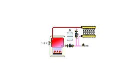
Figure 1 shows a hydronic system that's intended to supply four panel radiators, each with its own thermostatic radiator valve, and an indirect water heater from a gas-fired sectional cast-iron boiler.
An installer is asked to connect an old (but still working) propane-fueled cast-iron boiler, which was salvaged from another project, to a slab-on-grade floor heating system in a new workshop.
A contractor is asked to design a hydronic heating system for a modest, super-insulated house in a cold Northern climate. The home’s design load is only 18,000 Btu/h. The owners are planning to install a 12 KW solar photovoltaic electrical system.
An installer sets up a zoned distribution system as shown below. To keep it simple, he uses the same size piping for the headers and all the distribution circuits. The heat source is a low-mass, copper-tube boiler with high-flow resistance.
The schematic in Figure 1 represents a drawing I recently reviewed for a proposed system that was to supply three zones of finned-tube based, two zones of low-temperature radiant panel heating, and an indirect domestic water heater.