The Glitch & The Fix: Secondary issues

The Glitch:
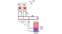
Sometimes multiple mistakes show up in small portions of hydronic systems. The piping configuration shown in Figure 1 is one example. It represents a simple secondary circuit within a primary/secondary system. Can you spot at least four specific installation details that could create problems within this system?
 Figure 1 (click to enlarge)
The Fix:
Because the system’s expansion tank is located in the primary loop, all secondary circuits “see” the primary loop as their point of no pressure change. Because of this, all secondary circulators should pump into their respective secondary circuits. The secondary circulator in Figure 1 is pumping out of the circuit. It’s also located very close to an elbow, which increases turbulence at the circulator’s inlet — not good. There should always be at least 10 diameters of straight pipe upstream of the inlet to any circulator. Figure 2 shows a properly positioned secondary circulator.
 Figure 2 (click to enlarge)
The installer has also located a ball valve between the two tees connecting the secondary circuit to the primary loop. Their reasoning is that temporarily closing the ball valve with force purging flow through the secondary circuit when the system is being filled. That’s true. The problem is the ball valve can’t be removed after purging. This valve, as well as the added space between the tees, creates a residual pressure drop that will try to induce flow in the secondary circuit anytime the primary circulator is on — even though the secondary circulator is off and there’s no demand for heat input to that specific secondary circuit. The solution is to install a standard purging valve near the return end of the secondary circuit as shown in Figure 2. This allows the tees to be located as close together as possible, minimizing any pressure drop between them. The purging valve also serves as an isolation valve for the secondary circuit if ever needed.
All secondary circuits also need a means of prevent heat migration into the circuit when it is not operating. A spring loaded check valve, either inside the secondary circulator or downstream of it, is a good check. An older-style flow-check valve is another possibility.
The original layout also doesn’t allow the secondary circuit to be isolated from the primary circuit. The configuration shown in Figure 2 does. Closing either of the circulator isolation flanges isolates the supply side of the secondary circuit. Closing the inline ball within the purging valve isolates the return side.
Download The Glitch & The Fix: October 2021 PDF
Looking for a reprint of this article?
From high-res PDFs to custom plaques, order your copy today!


.jpg")
