Hydronics Workshop | John Siegenthaler
Follow established piping layouts to prevent reverse thermosiphoning
Reversals revealed.

Image courtesy of alacatr / E+ / Getty Images.
I once heard a trainer tell a group of contractors that if you want water to follow the directional arrows on a schematic you have to draw arrows inside the pipe. That way the water can “see” the arrows and know what to do.
Most of the audience understood this was a very humorous but absurd suggestion. It’s the ones that didn’t perceive it that way that are the concern.
I’ve told groups of contractors that it’s “really important” when installing two circulators in a close-coupled series configuration that the arrows on both circulators point in the same direction. You probably think such a statement is unnecessary or even insulting, but I’ve seen three projects where this wasn’t done correctly.
Flow direction is certainly important in any hydronic system. In most proven hydronic system designs, flow direction is a certainty. However, there are some situations where the physics at work can turn things around. Let’s consider a few of these, and learn how to prevent them.
Reverse thermosiphoning
Whenever heated water is stored in a tank and there’s a piping path connecting the upper portion of that tank to the lower portion, heated water will “try” to move from the upper to the lower portion of the tank, as shown on the left side of Figure 1. This effect is called reverse thermosiphoning.
Figure 1
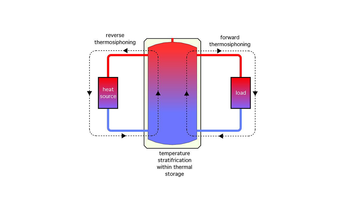
Reverse thermosiphoning is nature’s way of changing higher-grade energy (hot water in storage tank) into lower-grade energy (heat dissipated to cooler air around the heat source and piping).
The shape of the piping path connecting the upper to lower portions of the tank doesn’t matter. If there’s any unblocked piping path, reverse thermosiphoning will occur. Over a period of hours, it can drain much of the heat from the tank. The greater the surface area of the components forming the unblocked pathway, the higher the rate of heat dissipation.
A similar type of thermosiphoning is shown on the right (load) side of the tank in Figure 1. In this case, the undesired flow is in the same direction as the intended flow. This is called forward thermosiphoning.
Reverse thermosiphoning can be prevented by installing a check valve (swing check or spring-loaded check) in the piping, close to the upper connection point. Forward thermosiphoning can usually be stopped by installing a spring-loaded check valve (not a swing check) where the tank connects to the hot water side of the distribution system. Both corrective situations are shown in Figure 2.
Figure 2
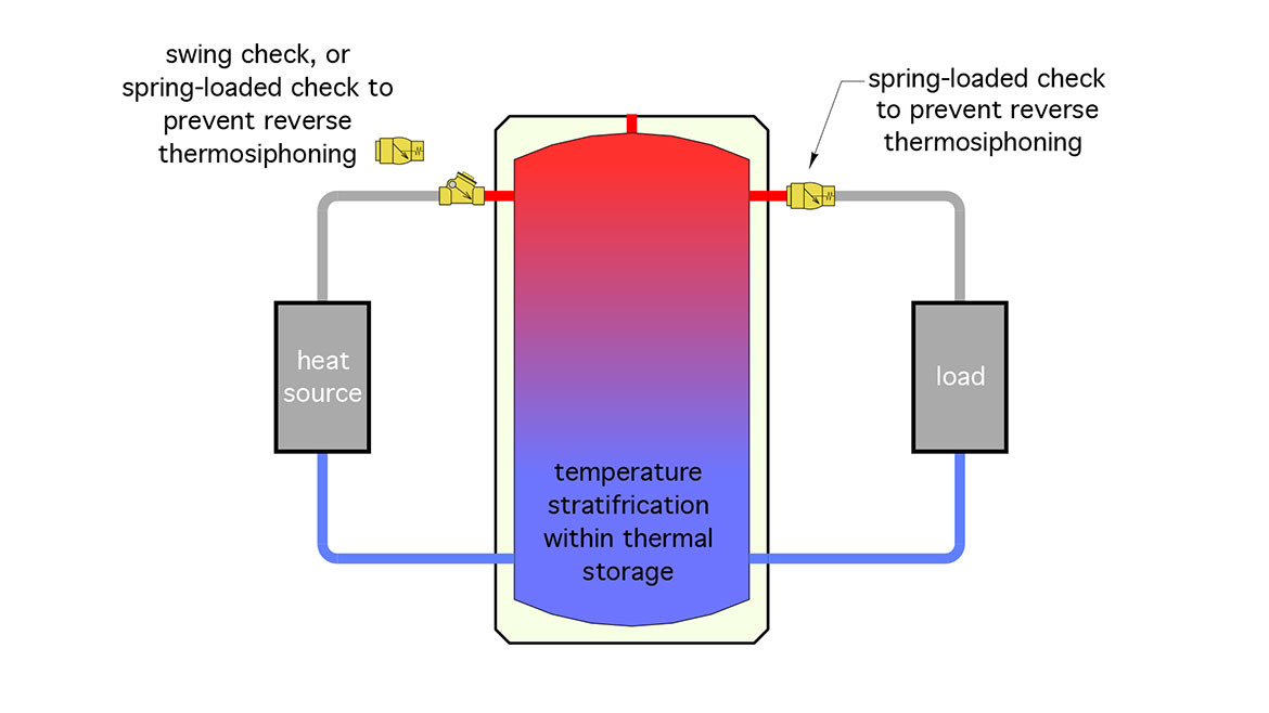
It’s also possible to prevent reverse or forward thermosiphoning by installing a motorized valve in the piping pathway, and configuring controls so that valve is closed whenever the piping pathway is inactive.
Dumb water
One method of zoning a hydronic system is to use a dedicated circulator for each zone. This approach has been used for decades, and it continues to be employed in both residential and commercial systems. A typical setup using this approach is shown in Figure 3.
Figure 3
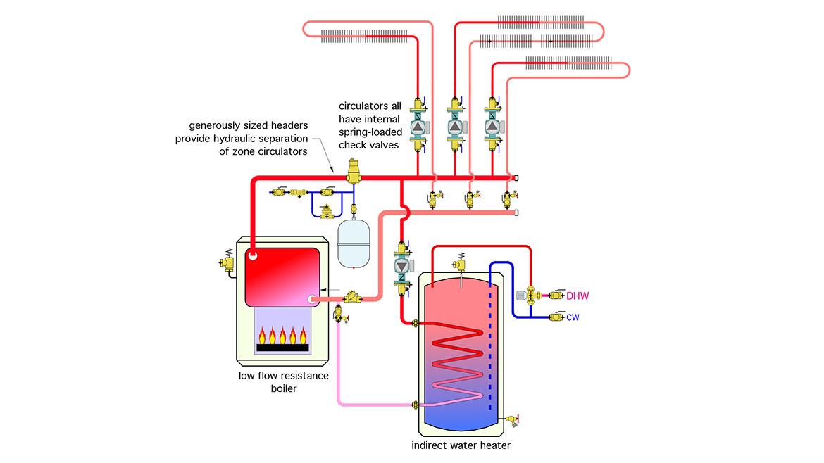
This system shows three space heating zones combined with a zone that supplies an indirect water heater. Similar systems could have more or less zones, but the underlying piping topology remains the same: all these systems have independently controlled circulators that are piped in parallel, and there are times when some circulators are on while others are off.
Consider what happens if we simplify this system down to two zones, leave out check valves and view it when only one circulator is running — see Figure 4.
Figure 4
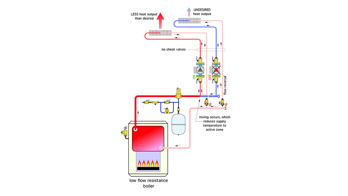
The problem begins at the tee where the active zone piping joins the return header. Although we’d like to think that all of the water at this point in the system is “smart enough” to flow back to the boiler to reload Btu, it isn’t. Instead, the water stream divides. Some flows back through the boiler as intended, but the rest flows backward through the inactive zone circuit. Without a check valve in that circuit there’s nothing to prevent this reverse flow.
The undesirable consequences of that reverse flow are twofold. First, heat is being dumped from the inactive zone circuit, possibly overheating its associated interior space. Second, the cooler water flowing backward through the inactive zone eventually mixes with the reheated water coming from the boiler. This reduces the supply water temperature into the active zone, reducing its heat output.
The solution is simple: install a check valve in each circuit, or, for small circulators, use the spring check cartridge insert that’s commonly shipped with these circulators.
The bottom line: every circulator that’s piped from a common header, buffer tank, hydraulic separator or any other “shared” piping component must have a check valve to prevent flow reversal.
Spring-loaded check valves are a good option to prevent reverse flow. Those sold for hydronic applications also have just enough forward opening resistance (about 0.5 psi) to prevent forward thermosiphoning through zone circuits when their associated circulators are off. The spring-loaded cartridges shipped with small circulators also have this nominal forward opening resistance.
The other option is to use a separate spring-loaded check valve installed at least 10 pipe diameters downstream of the circulator. This approach has a couple of potential benefits:
- It allows entrapped air bubbles to rise above the circulator’s impeller when the circulator is mounted in a vertical pipe with upward flow. This negates a potential problem in which air gets trapped within the circulator’s volute, under a check valve cartridge that is only an inch or two above the impeller. This scenario can occur when the system is first filled, especially if the system has not had a good forced-water purging. The trapped air hinders the circulator’s ability to purge itself. In essence, the circulator’s impeller cannot “grab onto” the entrapped air and hurl it upward out of the volute. By placing the check valve well above the circulator, the chances of such entrapped air are reduced.
- An external check valve with union connections can also be opened to clean or replace the spring-check cartridge if necessary.
“Unclosely" spaced tees
Primary/secondary systems in which pairs of closely-spaced tees (one for supply and the other for return) are installed along a piping loop provide hydraulic separation of all the circulators. However, they also create sequential temperature drops as flow in the primary loop gives up heat to each active secondary circuit.
To avoid this temperature drop effect, some installers have attempted to group all the supply side tees together and place them upstream of all the associated return tees, as shown in Figure 5.
Figure 5
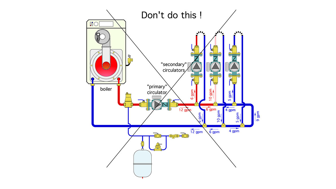
In theory, this piping arrangement could work — if and only if — the primary loop flow rate was always greater than or equal to the sum of the three load circuit flow rates. Although this is possible, making sure it happens would needlessly waste electrical power input to the required primary circulator. It’s a bad idea.
Whenever the primary loop flow is less than the sum of the three load circuit flows, there will be flow reversal in some portions of this system, even with check valves in all the secondary circuits. This is illustrated in Figure 5. The primary loop flow rate is 12 gpm, and the three load circuit flows are 6, 10, and 5 gpm.
To determine what happens in different segments of the piping just remember that what flows into a tee must flow out of the tee.
In this case, the 10 gpm flow rate into the middle circuit is achieved by combining 6 gpm from the left with 4 gpm from the right. The latter is cool water from the return side of load circuits. The mixing of 6 ppm of “hot” boiler water with 4 gpm of cooler return water will definitely reduce the supply water temperature to the middle load circuit. As if that weren’t bad enough, look what happens in the right side load circuit. The only way to satisfy the balance between incoming and outgoing flows is for 5 gpm of cool water to flow up through that circuit. Sure, there will probably be some heat output from that circuit, but the situation will only get worse as heat continues to be dissipated.
The way to avoid this is to not create the piping shown in Figure 5. Either create a true primary/secondary system where pairs of closely spaced tees are used to connect each secondary circuit to the primary loop, or, in my opinion, use the piping layout shown in Figure 6.
Figure 6
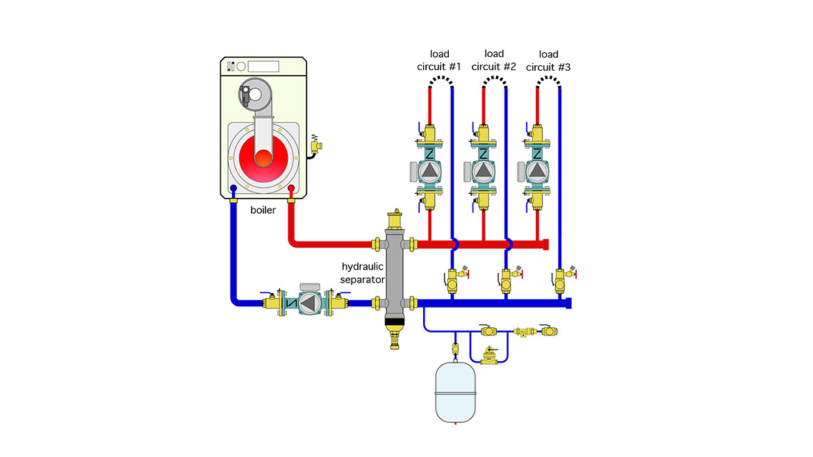
This approach provides the same supply water temperature to each load circuit, hydraulically separates all the circulators, and provides air and dirt separation. The check valves in the circulators prevent reverse flow regardless of which circulators are operating.
Be sure to size the load side headers for no more than 2 feet per second flow velocity when all the load circulators are operating. This “assists” the hydraulic separator in preventing undesired interaction between operating circulators.
Stick with what works
When you follow established piping layouts you won’t have to worry about unexpected flow reversal. You also won’t have to think about drawing those arrows on the inside of the piping…
Looking for a reprint of this article?
From high-res PDFs to custom plaques, order your copy today!


